
Auto Cooling System
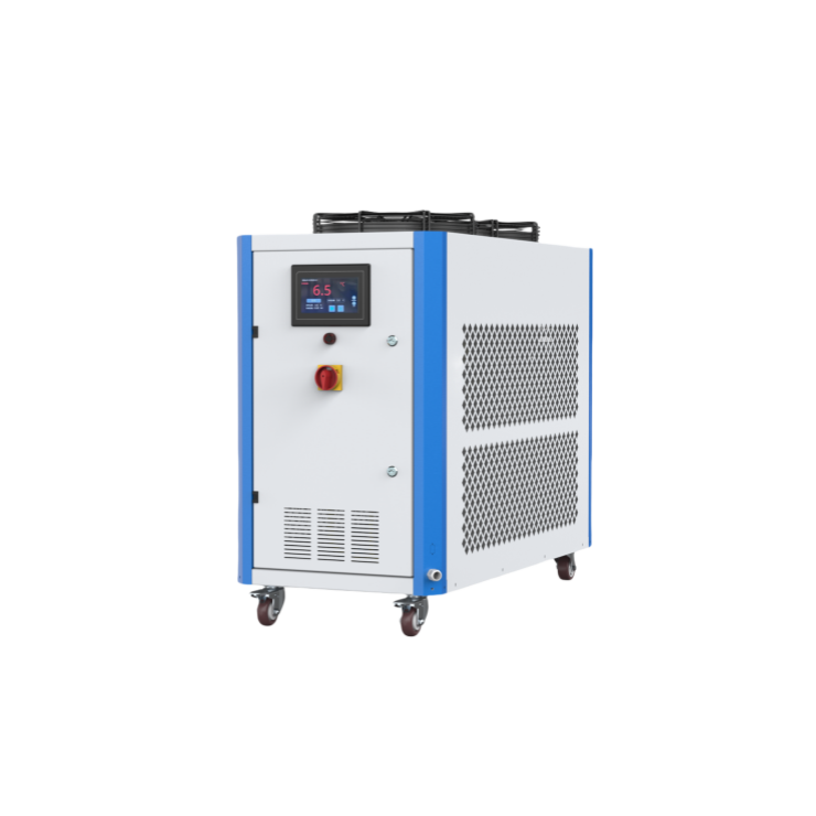
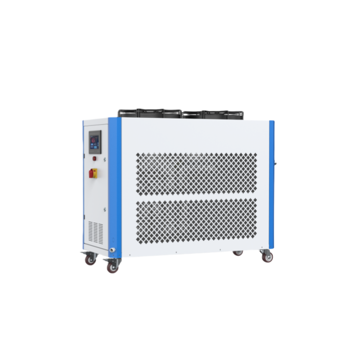
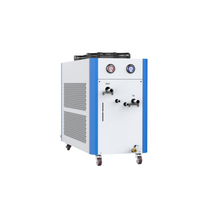
Topstar's cooling system is divided into two types. The water chiller uses a shell-and-tube condenser, which has fast heat conduction and good heat dissipation effect. It can provide chilled water at 5~35℃, and the low-temperature type can be as low as 3℃. The air chiller uses a fin-type condenser, which has fast heat conduction and good heat dissipation effect and does not require cooling water. It can provide chilled water at 5~35℃, and the low-temperature type can be as low as 3℃.
Features
- 1. It uses imported high-quality compressors and imported water pumps, which are safe, quiet, power-saving and durable.
- 2. Both water chillers and air chillers use full computer temperature controllers, which are simple to operate and can accurately control the water temperature at 5-35℃.
- 3. Both use current overload protection, high and low voltage control and electronic time delay safety devices, which will promptly issue an alarm and display the cause of the fault when a fault occurs.
- 4. The temperature of the ultra-low temperature chiller can reach below -10℃.
- 5. This series of chillers can be customized to be acid-resistant and alkali-resistant.
Application Industries
- 1. Electronics
- 2. Containers
- 3. 3C home appliances
- 4. Cosmetics
- 5. Auto parts
- 6. FMCG
Adequate supply of goods, available for delivery within 35 days.
Description
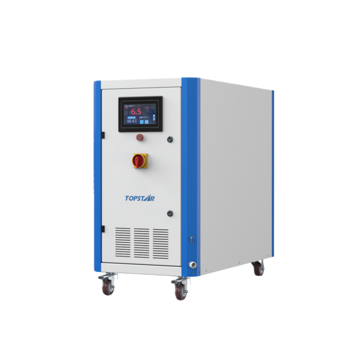
Water Chiller
Topstar Water Chiller is engineered for high-efficiency and energy-saving industrial cooling, making it ideal for injection molding and plastic processing applications. Featuring multi-compressor staged control, it delivers precise cooling performance while optimizing energy consumption across varying loads. The self-developed horizontal multi-stage centrifugal pump provides high flow rate, multi-stage pressure boosting, and low operating noise, significantly enhancing cooling efficiency. Its advanced coil design uses small-diameter parallel tubing, improving pressure resistance and accelerating heat exchange, while reducing welding points by 60% to minimize corrosion and leakage risks. Furthermore, this water chiller has a temperature control range of 5°C to 35°C and features a door interlock circuit breaker, ensuring stable cooling, long service life, and safe, reliable operation in demanding industrial environments.
Air Chiller
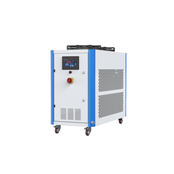
Topstar air chillers are designed for users who require flexible installation without the need for an external cooling water source. Equipped with a high-efficiency microchannel condenser, it reduces unit size by 20% while increasing heat transfer efficiency by 20%, resulting in faster and more effective cooling. High-quality brand compressors ensure low noise, stable performance, and reliable operation, while the coil-type evaporator minimizes ambient heat absorption, thus improving energy efficiency. The durable horizontal multi-stage centrifugal pump features a stainless steel pump head, providing high pressure and large flow rates. With a water temperature range of 5°C to 35°C, compressor power up to 50 HP, and four standard safety features, this air chiller provides a safe, efficient, and easy-to-install cooling solution for injection molding machines and industrial processes.
Open Type Water Chiller
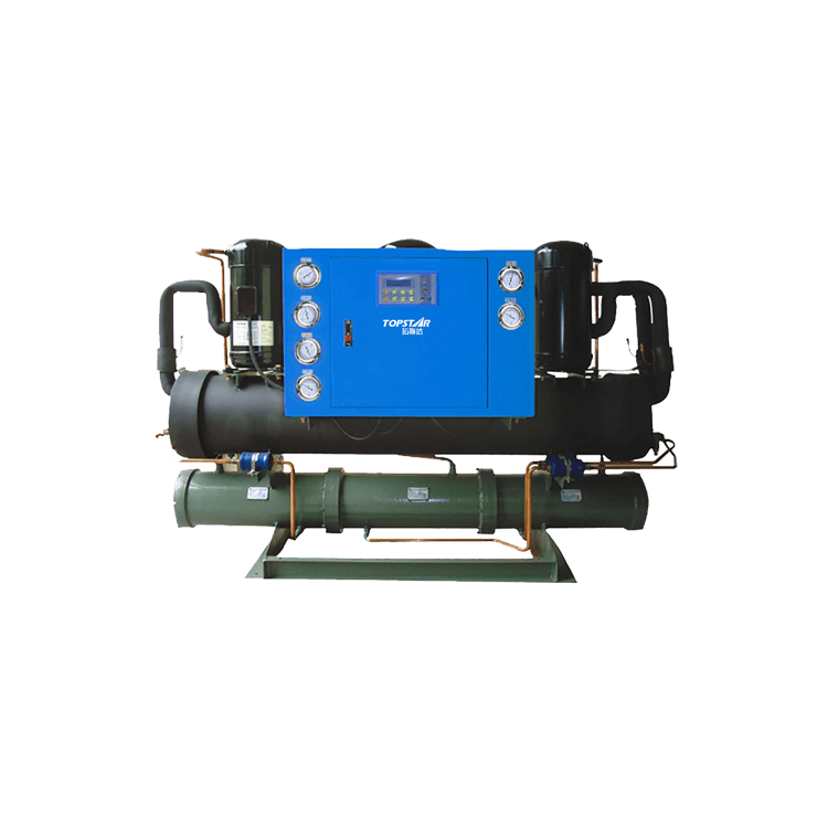
Open type water chiller units are designed for high-capacity industrial cooling applications requiring high power output and precise temperature control. With compressor power ranging from 30HP to 80HP, these units utilize high-quality compressors and water pumps to ensure quiet, energy-efficient, and durable operation. A fully computerized temperature controller precisely regulates water temperature from 5°C to 35°C, meeting the demanding cooling needs of applications such as injection molding and heavy industrial equipment. The specially designed condenser and evaporator structures provide superior heat transfer efficiency, while comprehensive safety features—including overload protection, high/low pressure control, phase-loss and reverse-phase protection, anti-freeze protection, and electronic delay alarms—ensure safe, stable, and reliable operation in continuous production environments.
Model Display
Case & Application
-
 1
1 -
 2
2 -
 3
3 -
 4
4 -
 5
5 -
 6
6 -
 7
7 -
 8
8