
Shorter cycle time
High-speed motors and lighter moving structures reduce time inside the mold.
INJECTION MOLDING ROBOT TECHNOLOGY
Topstar injection molding robots combine high-speed servo motion, mold-protection logic and expandable automation control—so every take-out, insert and downstream action runs with greater certainty.

WHY THE ROBOT MATTERS
An injection molding robot is a programmable linear automation system that enters the mold area to remove parts or sprues, place inserts, and coordinate downstream operations such as trimming, inspection, sorting and palletizing.
The right robot is selected by matching payload, stroke, take-out time, repeatability, end-of-arm tooling and communication requirements to the injection molding machine and the complete production process.
High-speed motors and lighter moving structures reduce time inside the mold.
Torque monitoring, ejector tracking and motion compensation protect the mold.
Expandable I/O and additional axes connect inserts, cutters and peripheral devices.
MES and wireless functions expose status, output, alarms and maintenance information.
SIX TECHNOLOGY FOUNDATIONS
Select a technology point to review the engineering evidence behind it.
TECHNOLOGY 01
Topstar develops the robot control system in-house. Software can be updated over the product lifecycle, custom actions can be developed for special processes, and the same platform can coordinate non-standard automation equipment.
 Topstar technical component
TECHNOLOGY 02
USB and RJ45 communication simplify wiring while supporting precise closed-loop control and strong interference resistance. The architecture can be configured with different motor platforms according to project requirements.
 Servo motion platform
TECHNOLOGY 03
The standard program retains at least 11 inputs and 11 outputs for expansion. A standard 4-suction/4-clamp configuration can be expanded to 8 suction or 8 clamp circuits for insert loading, trimming and peripheral interlocks.
Expandable control architecture
TECHNOLOGY 04
Forward and reverse control for the ejector and core pull is built in. When the product has not been removed, the controller prevents unsafe return actions to reduce the risk of mold, ejector-pin and part damage.
 Mold protection technology
TECHNOLOGY 05
The robot teaching program supports up to 1,500 instruction lines, while the handheld controller can store up to 100 production programs—useful for plants running many molds and product variants.
Teaching program interface
TECHNOLOGY 06
Topstar’s wireless production platform enables remote review of robot status, output and maintenance information, helping production teams improve factory visibility and reduce manual management effort.
 Smart manufacturing platform
PRODUCT PLATFORM
Choose the platform according to the production constraint that matters most: speed, balanced performance, dependable general automation or heavy-load flexibility.
High-speed, high-precision take-out
Lightweight A6061 main-arm construction, rack-and-pinion front/rear transmission and vibration suppression support fast, stable removal and insert placement.
Balanced speed, rigidity and automation
A practical high-performance choice for continuous production, multi-point tooling and lines that need MES and peripheral equipment connectivity.
Safe, dependable general automation
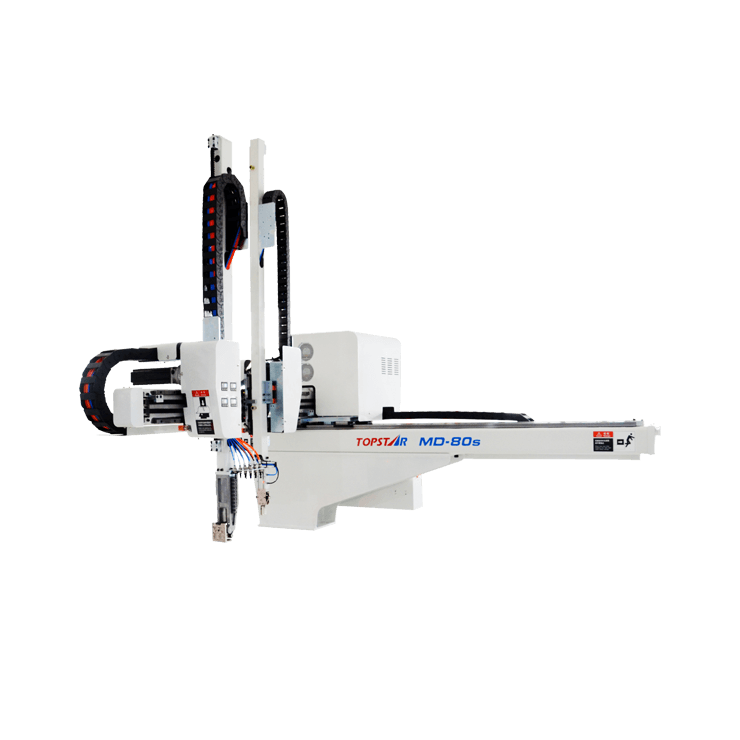
Designed for reliable day-to-day take-out with mold protection, physical anti-tip protection and flexible automation expansion.
Large parts, heavy loads and inserts

Dual guide rails, six-slider front/rear-arm support and expandable C/AC/BC axes create a rigid platform for heavy tooling and non-standard insert processes.
HOW TO CHOOSE
A correct injection molding robot selection protects cycle time, tooling and future automation capacity. Use the first filter below to identify a platform, then validate the seven engineering inputs with the application team.
RECOMMENDED STARTING POINT
Choose T1 when minimum time inside the mold and stable precision at high speed are the dominant requirements.
Engineering note: this is a first-stage guide. Final selection requires complete machine, mold, part, tooling and cell-layout data.
RECOMMENDED STARTING POINT
Choose T3 when production needs a practical balance of speed, rigidity, payload and automation connectivity.
Engineering note: this is a first-stage guide. Final selection requires complete machine, mold, part, tooling and cell-layout data.
RECOMMENDED STARTING POINT
Choose T4 for dependable take-out and straightforward automation where mold protection and safety are the priorities.
Engineering note: this is a first-stage guide. Final selection requires complete machine, mold, part, tooling and cell-layout data.
RECOMMENDED STARTING POINT
Choose MBW for high-tonnage machines, long strokes, heavy end-of-arm tooling and multi-axis insert or downstream processes.
Engineering note: this is a first-stage guide. Final selection requires complete machine, mold, part, tooling and cell-layout data.
IMM tonnage, tie-bar spacing, mold height, opening stroke and ejector arrangement.
Vertical, crosswise and traverse travel plus placement height and safe clearances.
Part, sprue, inserts, gripper, sensors and the center of gravity under acceleration.
Mold-open window, minimum take-out time and the total dry-cycle requirement.
Repeatability requirement, insert tolerance and release path from the mold.
Suction/clamp points, C/AC/BC axes, feeders, cutters, inspection and palletizing.
IMM signals, spare I/O, MES communication, wireless monitoring and safety logic.
SERIES DECISION MATRIX
This matrix translates Topstar’s robot platform differences into a practical purchasing decision. Exact model specifications should be confirmed against the final cell design.
| Decision point | EU / EUW | MDE / MEWE | TMDE / TMEWE | MBW / MBWE |
|---|---|---|---|---|
| Primary advantage | Maximum speed and precision | Balanced high performance | Practical safety and flexibility | Heavy-load, long-stroke automation |
| Best process fit | Fast take-out, precise inserts | Continuous multi-task production | General part and sprue removal | Large parts, inserts and downstream work |
| Motion evidence | 3 m/s; 6,500 r/min motor | 2.8 m/s; 750 W platform | Ejector tracking and anti-tip limit | 30% higher arm-motor power |
| Structural evidence | A6061 arm; 200 × 150 mm travel beam | 20% higher rigidity; lower vibration | Safety-focused classic platform | Dual guide rails; six-slider support |
| Automation expansion | High-precision take-out / insert | MES, 8S / 8C and special commands | MES, 8S / 8C and special commands | C, AC and BC axis options |
MBWE PLATFORM EVOLUTION
For large injection molding machines, the MBWE V platform combines increased motor power, longer stroke options and motor-driven arm motion. The performance figures below come from Topstar’s technical presentation.
Take-out time is a model performance reference; actual cycle performance depends on mold, stroke, payload, tooling and motion path.
PROVEN APPLICATION RANGE
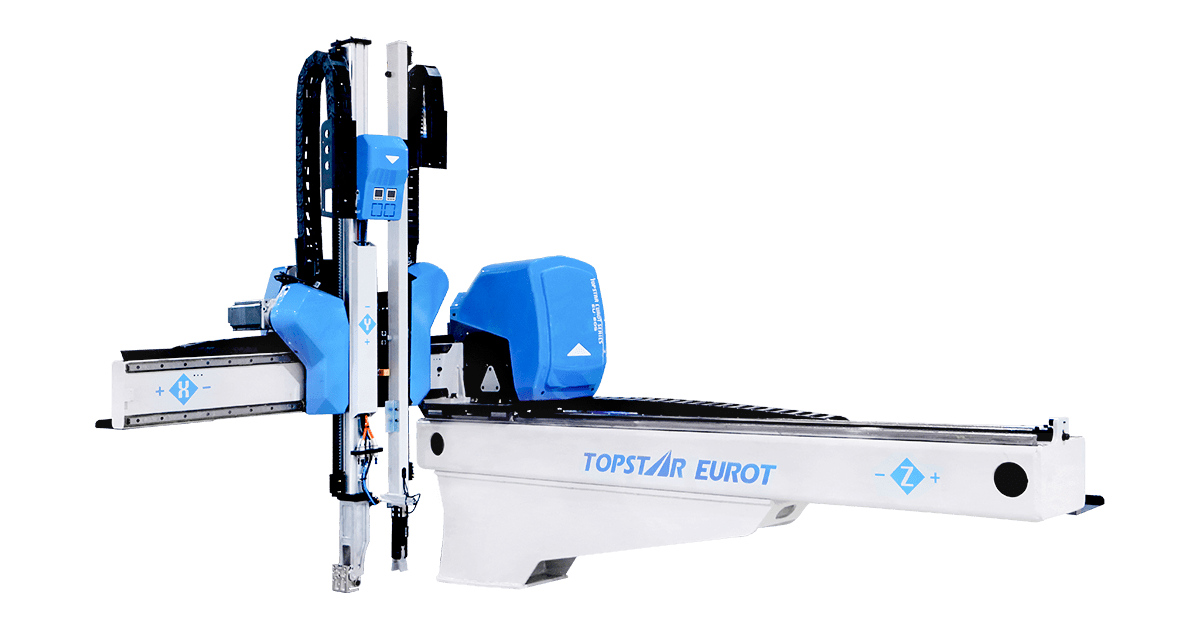
Topstar robot platforms support 3C electronics, home appliances, automotive parts, daily necessities, medical products and new-energy manufacturing.

TECHNICAL FAQ
Clear answers for early-stage specification. Final configuration is confirmed from project data and application review.
Start with the injection molding machine tonnage and mold-opening geometry, then confirm vertical, crosswise and traverse strokes. Calculate the combined weight of the molded part, sprue and end-of-arm tooling, add a safe payload margin, and finally verify take-out time, repeatability, I/O and any MES or downstream-equipment requirements.
Do not size the robot by part weight alone. Include the gripper, vacuum components, sensors, inserts and cables. A project engineer should also check the center of gravity and motion profile because an offset load at high acceleration can be more demanding than the same static weight close to the arm.
Three-axis servo control suits precise take-out and placement along linear paths. A 5-axis configuration is preferred when the process needs more flexible orientation, insert loading, complex release angles or coordinated downstream placement. C, AC or BC axes can extend MBW systems for special tooling.
The control platform combines servo torque monitoring, ejector tracking, mold-opening position compensation and ejector/core-pull interlocks. These functions help the robot respond to deviations and prevent unsafe actions before the product has been removed.
Yes. The standard program keeps at least 11 inputs and 11 outputs available for expansion, and suction/clamp circuits can be expanded for multi-point tooling. The robot can interlock with insert feeders, cutters, conveyors, inspection devices and factory information systems.
Provide the injection molding machine model and tonnage, mold dimensions, platen and opening data, product and sprue weight, end-of-arm tooling concept, required take-out and cycle times, placement layout, insert or trimming steps, utility standards and communication requirements.
APPLICATION ENGINEERING
Share your machine, mold, part, cycle and downstream-process data to receive a robot platform and configuration recommendation.