How to choose the screw and barrel configuration for your injection moulding machine?
- Injection moulding machine
- injection moulding machines
- plastic injection moulding machine
- plastic injection moulding machines
2025/07/16 By Topstar
Selecting a screw and barrel configuration for an injection moulding machine requires consideration of multiple factors, including polymer type, target shot size, cycle time requirements, and final part specifications. First, we need to evaluate the melt flow index, moisture sensitivity, and thermal stability of the product raw material, which determine the necessary plasticising capacity and affect the shear requirements of the screw. Then, consider the production volume and the complexity of the parts produced. Additionally, environmental operating conditions and temperature control accuracy in the barrel will also impact the heat transfer efficiency and melt uniformity. At the same time, we need to match the screw geometry, length-to-diameter ratio (L/D), and compression curve of the plastic injection moulding machine with these key parameters to ensure stable melt quality.
Material Properties and Screw Selection for Injection Moulding Machine
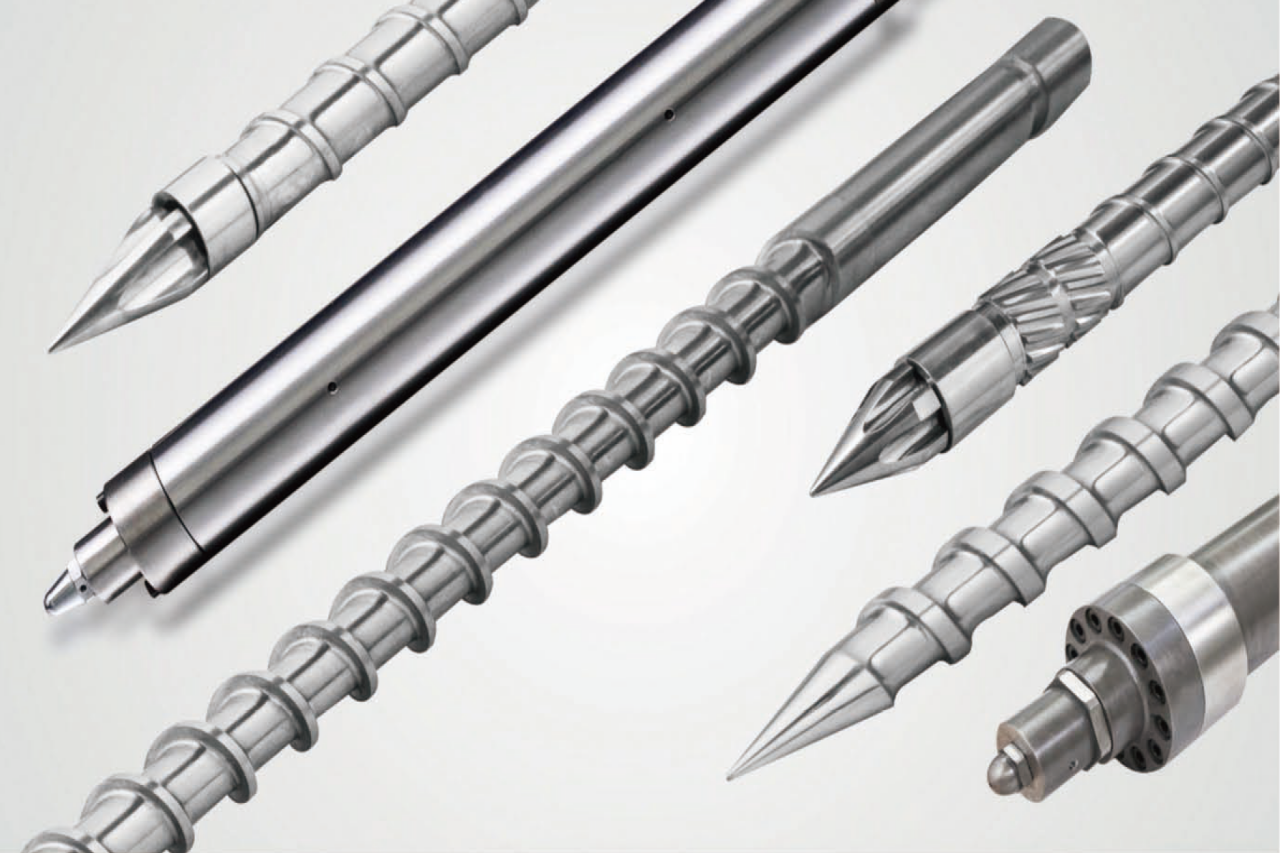
When configuring the screw and barrel of an injection moulding machine, the first step is to match the screw design to the material properties. For example, amorphous resins such as ABS require moderate shear and high back pressure, so a compression ratio of 2.5:1 to 3:1 is recommended to ensure proper melting without degradation. Additionally, semi-crystalline polymers, such as polypropylene, benefit from lower shear rates to prevent over-orientation, so compression ratios closer to 2:1 are preferred. We select screw flight and root diameters based on the melt viscosity of the resin to ensure uniform melt and minimal residence time. Additionally, hygroscopic polymers such as PET or nylon often require the use of a barrier or mixing screw to break up the water and achieve a uniform melt, reducing the risk of hydrolysis and part defects.
Shot Size, Plasticization Rate, and Length-to-Diameter Ratio
Next, shot size and desired throughput determine the length-to-diameter (L/D) ratio and diameter selection of the screw in the injection moulding machine. In addition to the baseline shot size calculation, cycle time goals also affect the desired plasticization rate. Therefore, an L/D ratio of 20:1 may be ideal for standard applications, while high-throughput systems often use ratios of up to 30:1 to enhance melt capacity and feed efficiency. We calculate the required screw diameter by dividing the maximum shot weight by the specific volume of the material and the target throughput, ensuring the screw can handle the necessary mass during the cooling and injection stages. This approach balances injection speed, melt uniformity, and energy consumption on a plastic injection moulding machine, while also considering factors such as regrind percentage and barrel fill level to prevent under- or over-plasticization.
Screw Geometry for Injection Moulding Machine
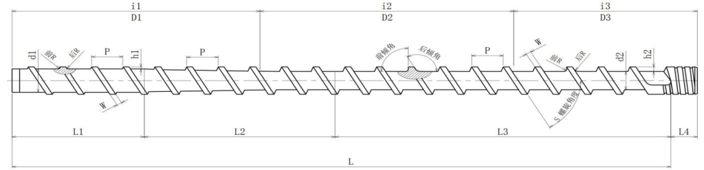
Optimising screw geometry enables consistent melt quality on an injection moulding machine. For example, a three-zone screw (feed, compression, metering) with a compression ratio of 3:1 provides a sharp melt profile for most thermoplastics. Thus, materials that require thorough mixing, such as filled or coloured compounds, benefit from a Maddock or barrier mixing section integrated into the metering zone. At the same time, we configure mixing elements based on filler content and desired dispersion, ensuring that the screw produces a uniform melt without excessive shear heating. Additionally, a mixing screw with separate channels can handle highly fibre-reinforced materials, preventing fibre breakage and maintaining the mechanical properties of the final part. Customizing the screw geometry to the part requirements can further improve the injection process.
Barrel Heating Zones and Venting Considerations
In addition to the screw, the barrel heating and venting configuration can significantly affect the performance of an injection moulding machine. Dividing the barrel into multiple independently controlled heating zones improves melt temperature uniformity across the entire screw length. Additionally, installing a vacuum vent in the feed section removes volatiles from moisture-sensitive resins, thereby enhancing the clarity of the final part. We set zone temperatures based on the resin’s melt curve and use thermocouple feedback to maintain ±2°C accuracy. Proper venting locations ensure that the melt does not leak out when venting, maintaining screw integrity and preventing flow instabilities. Optimising barrel insulation and heater band power further improves energy efficiency and reduces process variability.
Special configurations for advanced applications
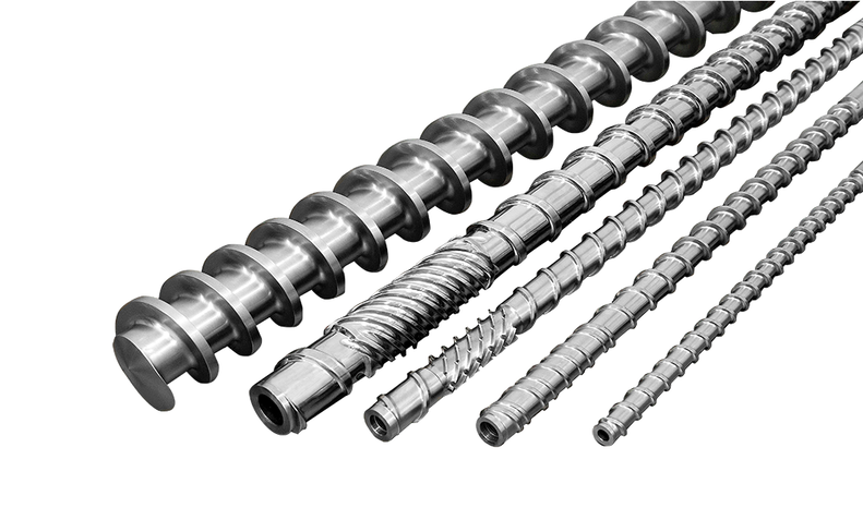
Certain high-performance parts require specialised screw and barrel configurations on the plastic injection moulding machine. In addition to barrier screws for moisture control, co-rotating twin screws can be used to process reactive or high-viscosity materials. As a result, plastic injection moulding machines can perform on-site compounding or masterbatch mixing without the need for separate extrusion equipment. I would recommend a custom-designed variable-pitch screw to optimise the shear profile for processing demanding engineering plastics, such as PEEK or high-impact polycarbonate. Spring-assisted check valves and extended nozzle assemblies further improve backflow prevention and shot consistency for micro moulding applications. Wear-resistant bimetallic barrels and nitrided screws extend service life when processing abrasive fillers such as glass fibre or mineral reinforcements.
Screw and barrel selection
The screw and barrel configuration for your injection moulding machine is tailored to account for material properties, shot size, machine throughput, mixing needs, and product requirements. We select screw aspect ratios, compression and mixing elements, and barrel zone controls based on empirical data, rigorous testing, and product-specific performance criteria. By applying a structured decision matrix and utilising specialised configurations, you can ensure consistent melt quality, optimised cycle times, and superior part performance.
TRENDING POSTS
- TOPSTAR Global Open Day 2025: Humanoid Robot Debuts, Pioneering a New Decade of Intelligent Manufacturing 2025/07/16
- Topstar Showcases TE II Electric Injection Molding Machines at InterPlas Thailand 2025 2025/07/16
- Topstar Expands Its Ecosystem Partnerships to Drive Smart Manufacturing Innovation 2025/07/16
- What factors can cause delays in the injection molding process of plastic molding machine? 2025/07/16
HOT TOPIC
- .ervo motor-driven linear robots
- •
- 1.0 guangdong topstar technology co. ltd
- 1.0 topstar china
- 1.0 topstar robot
- 11
- 160℃ mold temperature controller
- 170 ton injection molding machine
- 2
- 21
- 220-ton injection molding machine
- 23
- 260 ton injection molding machine
- 3 axis robot
- 3 axis robots
- 3 in 1 Compact Dehumidifying Dryer
- 3-axis robot
- 3-axis robots
- 39
- 41
- 460T injection molding machine
- 5-axis CNC machine
- 62
- 90 ton injection molding machine
- accuracy
- Air Chillers
- all electric injection molding machine
- all electric injection molding machines
- all-electric injection molding machine
- All-electric injection molding machines
- and overall production quality. Therefore
- AP-RubberPlas
- auto loader
- automated injection molding machine
- Automation changed engineering
- automation of injection molding robots
- automotive parts injection molding
- Auxiliary Equipment
- auxiliary machine
- Bench Injection Molding Machine
- cabinet dryer
- Cabinet dryer manufacturers
- Cabinet dryers
- chiller
- CNC Drilling Machine
- CNC Drilling Machines
- cnc engraving machine manufacturer
- cnc laser cutting machine manufacturer
- CNC machine
- CNC Machine Center
- CNC Machine for Sale
- CNC Machine Manufacturing
- CNC Machine Tool
- CNC machine tool product
- CNC Machining Center
- CNC wood carving machine
- Cooling system
- Cross-Walking Single Axis Servo Cylinder Robot
- Cross-Walking Single-Axis Servo Cylinder Robot
- Cross-Walking Three-Axis/Five-Axis Servo Driven Robot
- cross-walking three-axis/five-axis servo-driven robot
- Dehumidifier Dryer
- Dehumidifying Dryer
- delta parallel robot
- Desktop Injection Molding Machine
- Desktop injection molding machines
- Desktop Molding Machine
- desktop plastic injection machine
- Desktop Plastic Injection Molding Machine
- Digital Transformation
- direct clamp injection molding machine
- Direct clamp injection molding machines
- Dosing & mixing system
- Drilling Centers
- Drying and dehumidification system
- drying and dehumidifying equipment
- Drying and Dehumidifying System
- drying system
- effective and efficient. Cabinet dryers are also used in other industries where large quantities of material need to be dried
- efficient injection molding machine
- elbow hydraulic injection molding machines
- electric injection molding machine
- electric injection molding machines
- energy-efficient injection molding robot
- energy-efficient water chiller
- energy-efficient water chillers
- energy-saving injection molding machine
- etc. Among injection molding robots
- exhibition
- features of CNC machine
- Feeding And Conveying System
- Five Axis Machine Center
- Flexible Production Line
- Fully automatic injection molding machine
- Gathering Topstar
- giant injection molding machine
- GMU-600 5-Axis Machining Center
- Granulating & Recycling System
- granulator machine
- gravimetric blender
- Heavy duty injection molding machine
- High-precision electric molding machines
- high-precision plastic molding machines
- high-speed all electric injection molding machine
- high-speed electric injection molding machine
- High-Speed Packaging Injection Molding
- Honeycomb rotor dehumidifier
- Hopper Dryers
- horizontal injection molding machine
- Horizontal Injection Molding Machines
- Horizontal Injection Moulding Machine
- Horizontal Mixer manufacturer
- How The CNC Machine Works
- hybrid injection molding machine
- hydraulic injection molding machine
- Hydraulic Injection Molding Machines
- in this article
- Industrial AI
- Industrial Automation
- Industrial robot
- Industrial Robot Chinese brand
- industrial robot parts
- industrial robot supplier
- Industrial robots
- Industry Chain
- Injection Manipulator
- injection manipulator robot
- injection mold machines
- Injection molding
- Injection molding automation
- Injection Molding Automation Solution
- injection molding dryer
- Injection molding equipment
- injection molding hopper dryer
- Injection molding machine
- injection molding machine brand
- Injection Molding Machine Factory
- Injection Molding Machine Manufacture
- Injection molding machine manufacturer
- injection molding machine manufacturers
- Injection molding machine procurement
- injection molding machine robotic arm
- injection molding machine with a robot
- Injection molding machines
- injection molding material dehumidifying
- injection molding plant
- injection molding process
- Injection Molding Robot
- injection molding robot arm
- Injection molding robot automation
- Injection molding robotic arm
- injection molding robots
- injection moulding dryer
- Injection moulding machine
- injection moulding machines
- Injection Moulding Robots
- Injection Robot
- Injection robot arm
- Injection robot manufacturer
- Injection robot wholesale
- injection robots
- Intelligent Factory
- intelligent injection molding machines
- Intelligent Manufacturing
- intelligent mold temperature
- intelligent mold temperature controller
- Intelligent mould temperature controller
- InterPlas Thailand 2025
- Introducing Injection Robot
- It is the best choice for drying large quantities of material at once. Cabinetmakers use these machines because they are fast
- Large flow water type mold temperature controller
- large injection molding machine
- large injection molding machines
- Learn what industrial automation and robotics is
- linear robot
- linear robots
- low speed sound-proof granulator
- machine plastic molding
- make sure to add some! Improvements (2) Keyphrase in introduction: Your keyphrase or its synonyms appear in the first paragraph of the copy
- manipulator machine
- manufacturing
- Manufacturing Innovation
- medical grade injection molding machines
- Medical Injection Molding
- medical injection molding machine
- medical injection molding machines
- micro injection molding machine
- middle speed granulator
- Mini CNC machine manufacturers.
- mobile cover making machine
- Mold Temperature Control System
- mold temperature controller
- mold temperature controllers
- molding machine
- molding material Dehumidifying System
- mould temperature control system
- mould temperature controller
- mould temperature controllers
- New electric injection molding machine
- nitrogen dryer manufacturer
- nitrogen dryer system manufacturer
- Oil type mold temperature controller
- Oil type mold temperature controllers
- open day
- optical component injection molding
- Outbound links: No outbound links appear in this page. Add some! Images: No images appear on this page. Add some! Internal links: No internal links appear in this page
- packaging injection molding
- Packaging Solutions
- PET Preform injection molding
- phone case maker machine
- phone case making machine
- phone cover making machine
- PID Control Mold Temperature Controller
- plastic auto loader
- plastic bottle making machine
- plastic bottle manufacturing
- plastic bucket making machine
- plastic bucket manufacturing
- Plastic chair making machine
- plastic dryer for injection molding
- plastic forming equipment
- Plastic Granulators
- plastic hopper dryer
- plastic injection machine
- plastic injection machines
- plastic injection molding
- Plastic injection molding equipment
- Plastic injection molding machine
- Plastic Injection Molding Machines
- plastic injection moulding machine
- plastic injection moulding machines
- plastic injection robot
- plastic molding
- Plastic Molding Industry
- Plastic Molding machine
- plastic molding machine 1
- Plastic Molding Machines
- plastic molding press
- plastic moulding machine
- plastic phone case making machine
- plastic-molding machine
- powerful granulator
- Powerful Type Sound-Proof Granulator
- precision injection molding
- precision injection molding machines
- production of plastic seats
- pure water mould temperature controller
- Robot injection molding
- robot injection molding machine
- robot manufacturing companies
- Robotic arm for injection molding machine
- robotic injection molding machines
- robotics in injection molding
- SCARA robot
- SCARA robots
- Screw dosers
- Service-oriented manufacturing
- Servo Cylinder Robot
- servo driven robot
- Servo Driven Robots
- servo injection molding machine
- servo injection robots
- servo motor-driven linear robots
- servo-driven 3-axis robot
- Servo-driven injection molding machine
- Servo-Driven Robot
- Setup of injection machine
- Silicone Injection Molding Machine
- six-axis industrial robot
- Smart Manufacturing
- soundproof granulator
- Stainless Hopper Dryer
- Stainless Hopper Dryers
- star club
- swing arm robot
- take-out robot
- take-out robots
- Thailand 4.0
- the choice between servo-driven robots and hydraulic robots will have a certain impact on efficiency
- the most popular injection molding machine
- the type of injection molding robot
- TIC2000 Control System
- TMII injection molding machine
- toggle clamp injection molding machine
- Toggle Hydraulic Injection Molding Machines
- toggle injection molding machine
- Top 10 brands of injection robots
- Topstar
- Topstar Electric Injection Molding Machine InterPlas Thailand 2025 Smart Manufacturing Thailand 4.0
- Topstar Engineering
- Topstar Industrial Robots
- Topstar injection molding intelligent
- Topstar Scara Robots
- Useful Injection molding machine
- Vertical machining centers
- volumetric type blender
- water chiller
- water chillers
- water distributor
- water type mold temperature controller
- Water Type MoldTemperature Controller
- Water-Type Mould Temperature Controllers
- We often face choices when performing injection molding. We will choose the type of injection molding machine
- wholesale of injection molding machines
- x carve CNC
- 热门查询 点击次数 展示 排名 topstar