How to prevent overheating with proper mould temperature controller settings?
2025/06/06 By Topstar

When overheating occurs in injection moulding, it affects part quality and shortens equipment life. Mould temperature controller are the central system that regulates mould temperature during the injection cycle. By maintaining a precisely controlled thermal state, they ensure consistent part dimensions, avoid defects, and optimise cycle times. When mould overheating occurs, it is usually due to incorrect temperature setpoints, insufficient coolant flow, or improper control loop adjustment. As a result, the mould will be thermally unbalanced, causing the plastic to solidify too quickly to form hot spots. These hot spots not only reduce the surface finish of the part but also increase internal stress, causing premature wear and even damage to the mould.
Risk of overheating in mould temperature controller
Overheating usually comes from setpoints that are too high, improper coolant flow, or delayed control response. Additionally, fast cycle times and high injection pressures cause the heat generated in the mould to exceed the cooling system’s ability to dissipate it.
First, the injection moulding parameters will have a certain impact on the mould temperature, and the cooling channels must dissipate heat more quickly as the melt temperature increases. If the setpoint of the mould temperature controller is too close to or above the optimal solidification range of the polymer, the controller may struggle to maintain stability. As a result, the actual mould surface temperature may exceed the expected level, resulting in hot spots and local over-solidification. To avoid this, choose a mould temperature controller setpoint that reflects the polymer’s recommended processing window, typically 5-10°C below the material’s melting point, to ensure adequate heat dissipation without thermal stress.
Second, uneven temperature distribution can occur due to insufficient or inconsistent flow, which partially closed valves may cause, blocked cooling channels, or improperly sized pumps. As a result, some areas of the mould may not receive adequate cooling, prompting the mould temperature controller to increase the heater output to compensate, which in turn exacerbates overheating in other areas.
Optimal Mould Temperature Controller Temperature Settings
The mould temperature controller setpoint must be consistent with the processing requirements of the specific polymer, the thermal conductivity of the mould material, and the required cycle time. A temperature setting that is too low will prevent the polymer from filling properly, resulting in insufficient injection or premature solidification. Conversely, a temperature setpoint that is too high may cause the mould to overheat, resulting in flashing and other issues. Therefore, it is necessary to understand the range of polymer processing temperatures, for example, 20-40°C for crystalline materials, such as polypropylene, and 80-120°C for amorphous materials, such as ABS.
You should generally set the set point of the mould temperature controller near the middle of this range, as this ensures adequate flow for proper mould filling while preventing overheating. Second, consider the mould material and thickness. Steel moulds absorb and conduct heat more effectively than aluminium moulds. If using steel moulds with high thermal conductivity, you can set the temperature 5-10°C higher than the recommended minimum. Conversely, aluminium moulds tend to heat up and cool down faster; in this case, you can set the temperature a few degrees below the polymer’s midpoint to avoid local hot spots.

Flow and coolant considerations
After setting the temperature point, ensure adequate coolant flow. Even if you set the mould temperature controller accurately, insufficient or uneven coolant circulation can still cause hot spots. First, use an in-line flow meter to measure the actual flow and pressure drop of the mould coolant circuit. Compare these measurements with the design requirements of the mould. If the flow rate is below the recommended threshold, the mould temperature controller may have difficulty maintaining a uniform temperature. In this case, you should consider installing a dedicated coolant pump with adjustable speed control so you can precisely adjust the flow rate to meet the unique needs of each mould.
Second, minimise air entrapment in the coolant circuit. Air pockets can significantly disrupt the flow and create localised temperature zones. To prevent this, the piping layout should be designed with a gentle slope and a high-quality vent valve installed at the highest point in the loop. Before production begins, open the vent valve to exhaust air from the system until the coolant flows steadily out. It is also necessary to ensure that there is no air in the coolant loop, which allows the mould temperature controller to maintain consistent temperature readings and avoid erratic heating caused by local temperature differences caused by air.
PID parameter optimisation to ensure temperature stability
The PID control loop in the mould temperature controller minimises temperature overshoot and ensures rapid recovery from thermal disturbances. Suppose the PID settings are not appropriately adjusted. In that case, it will cause oscillation, where the mould temperature repeatedly exceeds and falls below the set point, or it will be sluggish to respond and unable to offset rapidly changing heat loads.
To optimise the PID settings on the mould temperature controller, first, observe the mould at ambient temperature, apply the necessary changes, and then increase the set point moderately. Observe how quickly and accurately the temperature approaches the new set point. At the same time, increase P until the temperature response shows slight oscillations, and then reduce P by 10% to 20% to achieve a stable, slightly underdamped response. Next, the integral time can be gradually increased to minimise the steady-state error. If the temperature reaches saturation with no oscillations when it is slightly above or below the setpoint, the integral term is close to the optimum value. The last step is to introduce a small derivative time to dampen any rapid changes. You can repeat the above steps to fine-tune P, I, and D until the response becomes smooth.

Take advantage of advanced control features
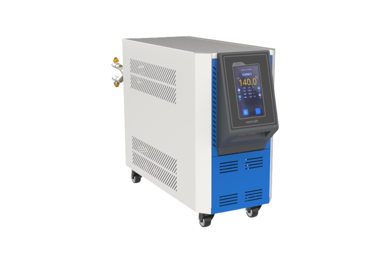
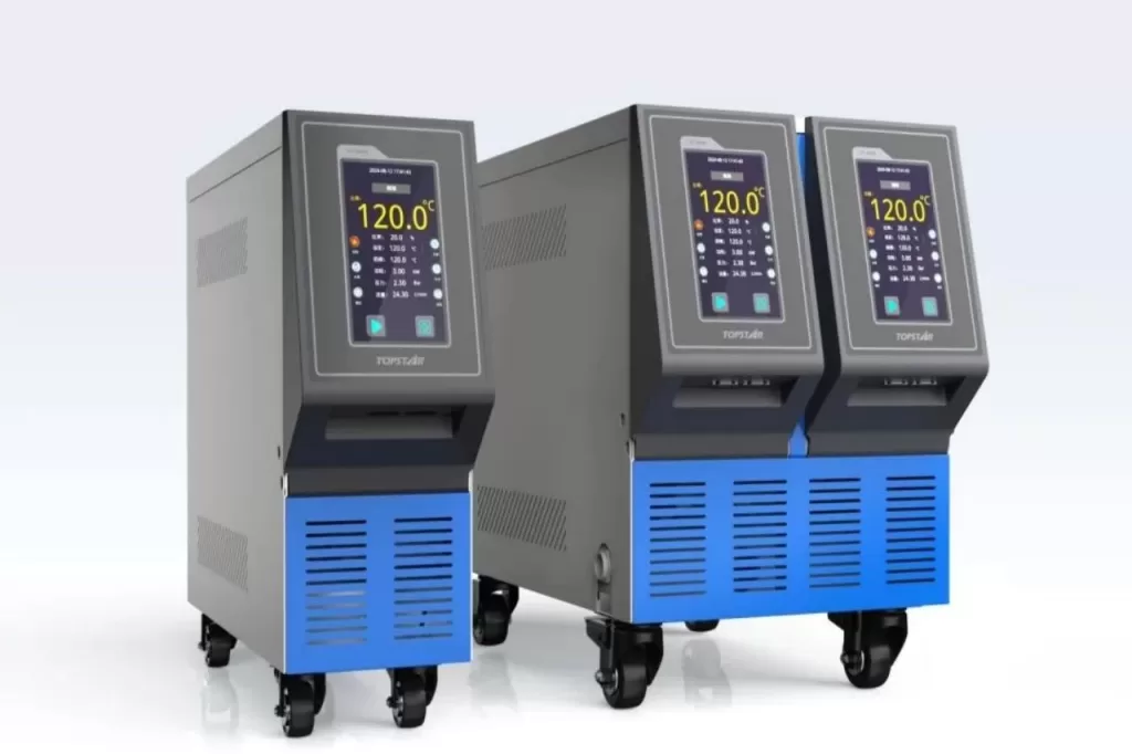
Topstar’s range of mould temperature controllers is equipped with a range of advanced features designed to prevent overheating further. In addition to basic PID control, these units often include features such as preheat scheduling, adaptive damping, automatic over-temperature alarms and remote monitoring.
Many moulds require a preheating phase before injection to ensure a uniform temperature distribution, especially for complex moulds or those with multiple materials. By programming a timed start-up preheating schedule directly into the mould temperature controller, heated coolant circulates through the mould at a low flow rate, gradually heating the tool. Ramping progressively up to the production set point minimises thermal shock and allows for uniform expansion of the metal.
Topstar equips its mould temperature controllers with an over-temperature alarm function to prevent uncontrolled temperature increases. When the temperature sensor in the mould detects a deviation exceeding a predetermined safety threshold, the controller triggers an audible and visual alarm on the machine interface to signal the injection moulding machine. This prevents the mould from reaching dangerously high temperatures. At the same time, under a unified control system, the mould temperature controller can be interconnected with the equipment, allowing for the remote monitoring of mould temperature in real-time. This enables the prevention of mould overheating and ensures production continuity.
Make appropriate settings to prevent overheating
Overheating poses a significant threat to injection moulding efficiency, part quality and mould life. Select set points based on polymer properties, mould materials, and geometric complexity. Ensure sufficient coolant pump capacity, adjust the PID, and utilise advanced functions to achieve robust and reliable thermal management. This approach prevents mould overheating, reduces scrap rates, and produces consistent, high-quality parts.
TRENDING POSTS
- TOPSTAR Global Open Day 2025: Humanoid Robot Debuts, Pioneering a New Decade of Intelligent Manufacturing 2025/06/06
- Topstar Showcases TE II Electric Injection Molding Machines at InterPlas Thailand 2025 2025/06/06
- Topstar Expands Its Ecosystem Partnerships to Drive Smart Manufacturing Innovation 2025/06/06
- What factors can cause delays in the injection molding process of plastic molding machine? 2025/06/06
HOT TOPIC
- .ervo motor-driven linear robots
- •
- 1.0 guangdong topstar technology co. ltd
- 1.0 topstar china
- 1.0 topstar robot
- 11
- 160℃ mold temperature controller
- 170 ton injection molding machine
- 2
- 21
- 220-ton injection molding machine
- 23
- 260 ton injection molding machine
- 3 axis robot
- 3 axis robots
- 3 in 1 Compact Dehumidifying Dryer
- 3-axis robot
- 3-axis robots
- 39
- 41
- 460T injection molding machine
- 5-axis CNC machine
- 62
- 90 ton injection molding machine
- accuracy
- Air Chillers
- all electric injection molding machine
- all electric injection molding machines
- all-electric injection molding machine
- All-electric injection molding machines
- and overall production quality. Therefore
- AP-RubberPlas
- auto loader
- automated injection molding machine
- Automation changed engineering
- automation of injection molding robots
- automotive parts injection molding
- Auxiliary Equipment
- auxiliary machine
- Bench Injection Molding Machine
- Cabinet dryer manufacturers
- Cabinet dryers
- chiller
- CNC Drilling Machine
- CNC Drilling Machines
- cnc engraving machine manufacturer
- cnc laser cutting machine manufacturer
- CNC machine
- CNC Machine Center
- CNC Machine for Sale
- CNC Machine Manufacturing
- CNC Machine Tool
- CNC machine tool product
- CNC Machining Center
- CNC wood carving machine
- Cooling system
- Cross-Walking Single Axis Servo Cylinder Robot
- Cross-Walking Single-Axis Servo Cylinder Robot
- Cross-Walking Three-Axis/Five-Axis Servo Driven Robot
- cross-walking three-axis/five-axis servo-driven robot
- Dehumidifier Dryer
- Dehumidifying Dryer
- delta parallel robot
- Desktop Injection Molding Machine
- Desktop injection molding machines
- Desktop Molding Machine
- desktop plastic injection machine
- Desktop Plastic Injection Molding Machine
- Digital Transformation
- direct clamp injection molding machine
- Direct clamp injection molding machines
- Dosing & mixing system
- Drilling Centers
- Drying and dehumidification system
- drying and dehumidifying equipment
- Drying and Dehumidifying System
- drying system
- effective and efficient. Cabinet dryers are also used in other industries where large quantities of material need to be dried
- efficient injection molding machine
- elbow hydraulic injection molding machines
- electric injection molding machine
- electric injection molding machines
- energy-efficient injection molding robot
- energy-efficient water chiller
- energy-efficient water chillers
- energy-saving injection molding machine
- etc. Among injection molding robots
- exhibition
- features of CNC machine
- Feeding And Conveying System
- Five Axis Machine Center
- Flexible Production Line
- Fully automatic injection molding machine
- Gathering Topstar
- giant injection molding machine
- GMU-600 5-Axis Machining Center
- Granulating & Recycling System
- granulator machine
- gravimetric blender
- Heavy duty injection molding machine
- High-precision electric molding machines
- high-precision plastic molding machines
- high-speed all electric injection molding machine
- high-speed electric injection molding machine
- High-Speed Packaging Injection Molding
- Honeycomb rotor dehumidifier
- Hopper Dryers
- horizontal injection molding machine
- Horizontal Injection Molding Machines
- Horizontal Injection Moulding Machine
- Horizontal Mixer manufacturer
- How The CNC Machine Works
- hybrid injection molding machine
- hydraulic injection molding machine
- Hydraulic Injection Molding Machines
- in this article
- Industrial AI
- Industrial Automation
- Industrial robot
- Industrial Robot Chinese brand
- industrial robot parts
- industrial robot supplier
- Industrial robots
- Industry Chain
- Injection Manipulator
- injection manipulator robot
- injection mold machines
- Injection molding
- Injection molding automation
- Injection Molding Automation Solution
- injection molding dryer
- Injection molding equipment
- injection molding hopper dryer
- Injection molding machine
- injection molding machine brand
- Injection Molding Machine Factory
- Injection Molding Machine Manufacture
- Injection molding machine manufacturer
- injection molding machine manufacturers
- Injection molding machine procurement
- injection molding machine robotic arm
- injection molding machine with a robot
- Injection molding machines
- injection molding material dehumidifying
- injection molding plant
- injection molding process
- Injection Molding Robot
- injection molding robot arm
- Injection molding robot automation
- Injection molding robotic arm
- injection molding robots
- Injection moulding machine
- injection moulding machines
- Injection Moulding Robots
- Injection Robot
- Injection robot arm
- Injection robot manufacturer
- Injection robot wholesale
- injection robots
- Intelligent Factory
- intelligent injection molding machines
- Intelligent Manufacturing
- intelligent mold temperature
- intelligent mold temperature controller
- Intelligent mould temperature controller
- InterPlas Thailand 2025
- Introducing Injection Robot
- It is the best choice for drying large quantities of material at once. Cabinetmakers use these machines because they are fast
- Large flow water type mold temperature controller
- large injection molding machine
- large injection molding machines
- Learn what industrial automation and robotics is
- linear robot
- linear robots
- low speed sound-proof granulator
- machine plastic molding
- make sure to add some! Improvements (2) Keyphrase in introduction: Your keyphrase or its synonyms appear in the first paragraph of the copy
- manipulator machine
- manufacturing
- Manufacturing Innovation
- medical grade injection molding machines
- Medical Injection Molding
- medical injection molding machine
- medical injection molding machines
- micro injection molding machine
- middle speed granulator
- Mini CNC machine manufacturers.
- mobile cover making machine
- Mold Temperature Control System
- mold temperature controller
- mold temperature controllers
- molding machine
- molding material Dehumidifying System
- mould temperature control system
- mould temperature controller
- mould temperature controllers
- New electric injection molding machine
- nitrogen dryer manufacturer
- nitrogen dryer system manufacturer
- Oil type mold temperature controller
- Oil type mold temperature controllers
- open day
- optical component injection molding
- Outbound links: No outbound links appear in this page. Add some! Images: No images appear on this page. Add some! Internal links: No internal links appear in this page
- packaging injection molding
- Packaging Solutions
- PET Preform injection molding
- phone case maker machine
- phone case making machine
- phone cover making machine
- PID Control Mold Temperature Controller
- plastic bottle making machine
- plastic bottle manufacturing
- plastic bucket making machine
- plastic bucket manufacturing
- Plastic chair making machine
- plastic dryer for injection molding
- plastic forming equipment
- plastic hopper dryer
- plastic injection machine
- plastic injection machines
- plastic injection molding
- Plastic injection molding equipment
- Plastic injection molding machine
- Plastic Injection Molding Machines
- plastic injection moulding machine
- plastic injection moulding machines
- plastic injection robot
- plastic molding
- Plastic Molding Industry
- Plastic Molding machine
- plastic molding machine 1
- Plastic Molding Machines
- plastic molding press
- plastic moulding machine
- plastic phone case making machine
- plastic-molding machine
- powerful granulator
- Powerful Type Sound-Proof Granulator
- precision injection molding
- precision injection molding machines
- production of plastic seats
- pure water mould temperature controller
- Robot injection molding
- robot injection molding machine
- robot manufacturing companies
- Robotic arm for injection molding machine
- robotic injection molding machines
- robotics in injection molding
- SCARA robot
- SCARA robots
- Service-oriented manufacturing
- Servo Cylinder Robot
- servo driven robot
- Servo Driven Robots
- servo injection molding machine
- servo injection robots
- servo motor-driven linear robots
- servo-driven 3-axis robot
- Servo-driven injection molding machine
- Servo-Driven Robot
- Setup of injection machine
- Silicone Injection Molding Machine
- six-axis industrial robot
- Smart Manufacturing
- soundproof granulator
- Stainless Hopper Dryer
- Stainless Hopper Dryers
- star club
- swing arm robot
- take-out robot
- take-out robots
- Thailand 4.0
- the choice between servo-driven robots and hydraulic robots will have a certain impact on efficiency
- the most popular injection molding machine
- the type of injection molding robot
- TIC2000 Control System
- TMII injection molding machine
- toggle clamp injection molding machine
- Toggle Hydraulic Injection Molding Machines
- toggle injection molding machine
- Top 10 brands of injection robots
- Topstar
- Topstar Electric Injection Molding Machine InterPlas Thailand 2025 Smart Manufacturing Thailand 4.0
- Topstar Engineering
- Topstar Industrial Robots
- Topstar injection molding intelligent
- Topstar Scara Robots
- Useful Injection molding machine
- Vertical machining centers
- volumetric type blender
- water chiller
- water chillers
- water distributor
- water type mold temperature controller
- Water Type MoldTemperature Controller
- Water-Type Mould Temperature Controllers
- We often face choices when performing injection molding. We will choose the type of injection molding machine
- wholesale of injection molding machines
- x carve CNC
- 热门查询 点击次数 展示 排名 topstar
