How to adjust the velocity profile of a 3-axis robot to avoid vibration?
2025/07/04 By Topstar
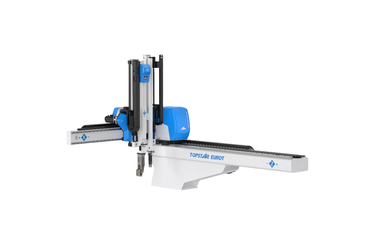
Designed for precision injection molding applications, 3-axis robots are designed explicitly for pick-and-place operations. If slight vibrations during part removal can affect quality, increase cycle time, and cause unplanned maintenance. Therefore, we integrate vibration suppression functions throughout the mechanical design and control firmware of the 3-axis robot, while also considering how to adjust the speed profile. First, sudden acceleration or deceleration in production can cause structural resonance in the arm and wrist. Second, improper adjustment of the motion segment can produce oscillations, which will reduce long-term reliability. By carefully designing the acceleration, constant speed, and deceleration phases, we can significantly reduce mechanical shocks.
Dynamics of a 3-axis robot integrated with injection molding
During the injection molding process, fast part ejection, pick-and-place movements, and different payloads generate dynamic loads. When accelerating a 2 kg molded part, the robot’s wrist and arm may be subjected to inertial forces of more than 15 kg·m/s²; in addition, the cantilever section of the arm is close to the resonant frequency of 3-5 Hz, and this minor disturbance can also be amplified into significant vibrations. Therefore, modal testing using accelerometers and shakers is performed during the design process to analyze each motion axis, identify resonance peaks, and quantify damping ratios. Based on this data, we defined the maximum allowed acceleration and jerk values for each segment. By modeling these dynamics in simulation tools such as MATLAB Simulink or ROS Gazebo, we ensured that the velocity profile prevented resonance amplification, allowing the 3-axis robot to perform high-speed, high-precision removals without causing harmful vibrations or reducing part accuracy.
Designing S-curve velocity profiles for smooth motion
Building on the 3-axis robot’s vibration suppression capabilities, we implemented S-curve velocity profiles, allowing acceleration and deceleration to change smoothly rather than abruptly. First, we calculated the maximum acceleration below the payload-specific resonance threshold. Then, I adjusted the acceleration profile to keep the acceleration rate within ±5000 mm/s³ to prevent sudden torque peaks from causing the end effector to bounce. Next, I wrote the motion planner for the 3-axis robot controller to interpolate velocities using a quintic polynomial, achieving seamless transitions between motion phases.
Additionally, I verified on the physical hardware that the peak torque demand did not exceed the motor rating, ensuring both the drive and the mechanism remained within a safe operating range. This strict S-curve implementation keeps the net forces on this type of injection molding robot structure within a safe range, resulting in smoother part pick-and-place cycles and eliminating micro-oscillations that reduce the accuracy of injection molding robots.
Segmenting Complex Paths of 3-Axis Robot to Reduce Vibration
The motions in the injection molding robot sequence are not all simple point-to-point moves, and complex trajectories can exacerbate vibrations if they are not appropriately segmented. At the same time, if not segmented, combining linear and joint interpolation motions can cause abrupt changes in velocity vectors; therefore, I decompose each multi-axis path into small linear or spline segments, each with an individually adjusted S-curve profile. Operators adjust the segment length to ensure each sub-move lasts over 100 milliseconds, giving the controller enough time to handle acceleration and avoid differential coordinate jumps. Additionally, we incorporate midpoint dwell commands in narrow corners to prevent centrifugal forces from shaking the robot arm. This fine segmentation, combined with real-time feedback monitoring of encoder ripple, prevents cumulative vibration and ensures that each part of the path maintains high accuracy.
Adaptive Real-Time Feedback and Vibration Correction
To further suppress vibration, our 3-axis robot controller integrates an adaptive real-time feedback loop into the motion control firmware. Our accelerometer, mounted on the robot’s wrist, continuously feeds vibration data into the controller. In addition, the control algorithm dynamically adjusts upcoming motion segments to suppress detected vibrations. We fine-tune the motion controller’s gains to prioritize vibration signals, cutting acceleration commands by 20% when they exceed thresholds. We also implement notch filters for identified resonant frequencies to attenuate end-effector wobble. By continuously analyzing the robot’s dynamic response, we dynamically adjust the velocity profile to ensure that each cycle compensates for subtle changes in payload, temperature, or wear, thereby maintaining consistent, vibration-free removal performance.
Practical Tips for Field Implementation
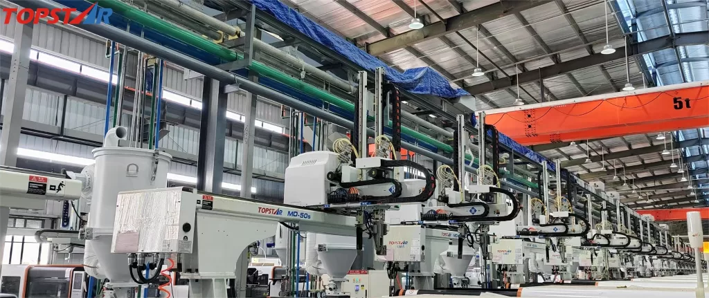
When deploying a 3-axis robot, engineers must consider several practical factors to ensure long-term vibration-optimized performance. First, perform a dry-run calibration at each new installation site to account for ground stiffness and anchoring conditions. Next, adjust acceleration and jerk parameters in 10% increments and monitor position errors using a laser tracker during initial runs. In addition, diagnostic tools are available to visualize velocity profiles and identify any “peaks” that may cause vibration. Additionally, technicians regularly recalibrate and conduct resonance tests to preserve S-curve setting integrity. This ensures your injection molding robot delivers flawless, vibration-free cycles while sustaining peak throughput.
Speed Profile Optimization
Adjusting the velocity profile of a 3-axis robot is crucial for preventing vibration and achieving high-precision performance in injection molding applications. Identify dynamic resonances, design S-curve motion segments, segment complex paths, and implement adaptive feedback to ensure smooth operation under any conditions. This will optimize your injection molding robot integration, increase production efficiency, and minimize scrap.
TRENDING POSTS
- CHINAPLAS 2026 is Coming Soon! 2025/07/04
- New Year, New Beginnings: Topstar Robotics Delivers Heartfelt Service to Keep Customers Thriving! 2025/07/04
- TOPSTAR Global Open Day 2025: Humanoid Robot Debuts, Pioneering a New Decade of Intelligent Manufacturing 2025/07/04
- Topstar Showcases TE II Electric Injection Molding Machines at InterPlas Thailand 2025 2025/07/04
HOT TOPIC
- .ervo motor-driven linear robots
- •
- 1.0 guangdong topstar technology co. ltd
- 1.0 topstar china
- 1.0 topstar robot
- 11
- 160℃ mold temperature controller
- 170 ton injection molding machine
- 2
- 21
- 220-ton injection molding machine
- 23
- 260 ton injection molding machine
- 3 axis robot
- 3 axis robots
- 3 in 1 Compact Dehumidifying Dryer
- 3-axis robot
- 3-axis robots
- 39
- 41
- 460T injection molding machine
- 5-axis CNC machine
- 62
- 90 ton injection molding machine
- accuracy
- Air Chillers
- all electric injection molding machine
- all electric injection molding machines
- all-electric injection molding machine
- All-electric injection molding machines
- and overall production quality. Therefore
- AP-RubberPlas
- auto loader
- automated injection molding machine
- Automation changed engineering
- automation of injection molding robots
- automotive parts injection molding
- Auxiliary Equipment
- auxiliary machine
- Bench Injection Molding Machine
- cabinet dryer
- Cabinet dryer manufacturers
- Cabinet dryers
- Cartesian Coordinate Robots
- chiller
- CNC Drilling Machine
- CNC Drilling Machines
- cnc engraving machine manufacturer
- cnc laser cutting machine manufacturer
- CNC machine
- CNC Machine Center
- CNC Machine for Sale
- CNC Machine Manufacturing
- CNC Machine Tool
- CNC machine tool product
- CNC Machining Center
- CNC wood carving machine
- Cooling system
- Cross-Walking Single Axis Servo Cylinder Robot
- Cross-Walking Single-Axis Servo Cylinder Robot
- Cross-Walking Three-Axis/Five-Axis Servo Driven Robot
- cross-walking three-axis/five-axis servo-driven robot
- Dehumidifier Dryer
- Dehumidifying Dryer
- delta parallel robot
- Desktop Injection Molding Machine
- Desktop injection molding machines
- Desktop Molding Machine
- desktop plastic injection machine
- Desktop Plastic Injection Molding Machine
- Digital Transformation
- direct clamp injection molding machine
- Direct clamp injection molding machines
- Dosing & mixing system
- Drilling Centers
- Drying and dehumidification system
- drying and dehumidifying equipment
- Drying and Dehumidifying System
- drying system
- effective and efficient. Cabinet dryers are also used in other industries where large quantities of material need to be dried
- efficient injection molding machine
- elbow hydraulic injection molding machines
- electric injection molding machine
- electric injection molding machines
- energy-efficient injection molding robot
- energy-efficient water chiller
- energy-efficient water chillers
- energy-saving injection molding machine
- etc. Among injection molding robots
- exhibition
- features of CNC machine
- Feeding And Conveying System
- Five Axis Machine Center
- Flexible Production Line
- Fully automatic injection molding machine
- Gathering Topstar
- giant injection molding machine
- GMU-600 5-Axis Machining Center
- Granulating & Recycling System
- granulator machine
- gravimetric blender
- Heavy duty injection molding machine
- High-precision electric molding machines
- high-precision plastic molding machines
- high-speed all electric injection molding machine
- high-speed electric injection molding machine
- High-Speed Packaging Injection Molding
- Honeycomb rotor dehumidifier
- hopper dryer
- Hopper Dryers
- horizontal injection molding machine
- Horizontal Injection Molding Machines
- Horizontal Injection Moulding Machine
- Horizontal Mixer manufacturer
- How The CNC Machine Works
- hybrid injection molding machine
- hydraulic injection molding machine
- Hydraulic Injection Molding Machines
- in this article
- Industrial AI
- Industrial Automation
- Industrial robot
- Industrial Robot Chinese brand
- industrial robot parts
- industrial robot supplier
- Industrial robots
- Industry Chain
- Injection Manipulator
- injection manipulator robot
- injection mold machines
- Injection molding
- Injection molding automation
- Injection Molding Automation Solution
- injection molding dryer
- Injection molding equipment
- injection molding hopper dryer
- Injection molding machine
- injection molding machine brand
- Injection Molding Machine Factory
- Injection Molding Machine Manufacture
- Injection molding machine manufacturer
- injection molding machine manufacturers
- Injection molding machine procurement
- injection molding machine robotic arm
- injection molding machine with a robot
- Injection molding machines
- injection molding material dehumidifying
- injection molding plant
- injection molding process
- Injection Molding Robot
- injection molding robot arm
- Injection molding robot automation
- Injection molding robotic arm
- injection molding robots
- injection molding whole plant
- injection moulding dryer
- Injection moulding machine
- injection moulding machines
- Injection Moulding Robots
- Injection Robot
- Injection robot arm
- Injection robot manufacturer
- Injection robot wholesale
- injection robots
- Intelligent Factory
- intelligent injection molding machines
- Intelligent Manufacturing
- intelligent mold temperature
- intelligent mold temperature controller
- Intelligent mould temperature controller
- InterPlas Thailand 2025
- Introducing Injection Robot
- It is the best choice for drying large quantities of material at once. Cabinetmakers use these machines because they are fast
- Large flow water type mold temperature controller
- large injection molding machine
- large injection molding machines
- Learn what industrial automation and robotics is
- linear robot
- linear robots
- low speed sound-proof granulator
- machine plastic molding
- make sure to add some! Improvements (2) Keyphrase in introduction: Your keyphrase or its synonyms appear in the first paragraph of the copy
- manipulator machine
- manufacturing
- Manufacturing Innovation
- medical grade injection molding machines
- Medical Injection Molding
- medical injection molding machine
- medical injection molding machines
- micro injection molding machine
- middle speed granulator
- Mini CNC machine manufacturers.
- mobile cover making machine
- Mold Temperature Control System
- mold temperature controller
- mold temperature controllers
- molding machine
- molding material Dehumidifying System
- mould temperature control system
- mould temperature controller
- mould temperature controllers
- New electric injection molding machine
- nitrogen dryer manufacturer
- nitrogen dryer system manufacturer
- Oil type mold temperature controller
- Oil type mold temperature controllers
- open day
- optical component injection molding
- Outbound links: No outbound links appear in this page. Add some! Images: No images appear on this page. Add some! Internal links: No internal links appear in this page
- packaging injection molding
- Packaging Solutions
- PET Preform injection molding
- phone case maker machine
- phone case making machine
- phone cover making machine
- PID Control Mold Temperature Controller
- plastic auto loader
- plastic bottle making machine
- plastic bottle manufacturing
- plastic bucket making machine
- plastic bucket manufacturing
- Plastic chair making machine
- plastic dryer for injection molding
- plastic forming equipment
- Plastic Granulators
- plastic hopper dryer
- plastic injection machine
- plastic injection machines
- plastic injection molding
- Plastic injection molding equipment
- Plastic injection molding machine
- Plastic Injection Molding Machines
- plastic injection moulding machine
- plastic injection moulding machines
- plastic injection robot
- plastic molding
- Plastic Molding Industry
- Plastic Molding machine
- plastic molding machine 1
- Plastic Molding Machines
- plastic molding press
- plastic moulding machine
- plastic phone case making machine
- plastic-molding machine
- powerful granulator
- Powerful Type Sound-Proof Granulator
- precision injection molding
- precision injection molding machines
- production of plastic seats
- pure water mould temperature controller
- Robot injection molding
- robot injection molding machine
- robot manufacturing companies
- Robotic arm for injection molding machine
- robotic injection molding machines
- robotics in injection molding
- SCARA robot
- SCARA robots
- Screw dosers
- Service-oriented manufacturing
- Servo Cylinder Robot
- servo driven robot
- Servo Driven Robots
- servo injection molding machine
- servo injection robots
- servo motor-driven linear robots
- servo-driven 3-axis robot
- Servo-driven injection molding machine
- Servo-Driven Robot
- Setup of injection machine
- Silicone Injection Molding Machine
- six-axis industrial robot
- Smart Manufacturing
- soundproof granulator
- Sprue Picker
- Stainless Hopper Dryer
- Stainless Hopper Dryers
- star club
- swing arm robot
- take-out robot
- take-out robots
- Thailand 4.0
- the choice between servo-driven robots and hydraulic robots will have a certain impact on efficiency
- the most popular injection molding machine
- the type of injection molding robot
- TIC2000 Control System
- TMII injection molding machine
- toggle clamp injection molding machine
- Toggle Hydraulic Injection Molding Machines
- toggle injection molding machine
- Top 10 brands of injection robots
- Topstar
- Topstar Electric Injection Molding Machine InterPlas Thailand 2025 Smart Manufacturing Thailand 4.0
- Topstar Engineering
- Topstar Industrial Robots
- Topstar injection molding intelligent
- Topstar Scara Robots
- Useful Injection molding machine
- Vertical machining centers
- volumetric type blender
- water chiller
- water chillers
- water distributor
- water type mold temperature controller
- Water Type MoldTemperature Controller
- Water-Type Mould Temperature Controllers
- We often face choices when performing injection molding. We will choose the type of injection molding machine
- wholesale of injection molding machines
- x carve CNC
- 热门查询 点击次数 展示 排名 topstar