How to plan the factory layout of multiple injection moulding equipment units?
2025/08/18 By le zhan
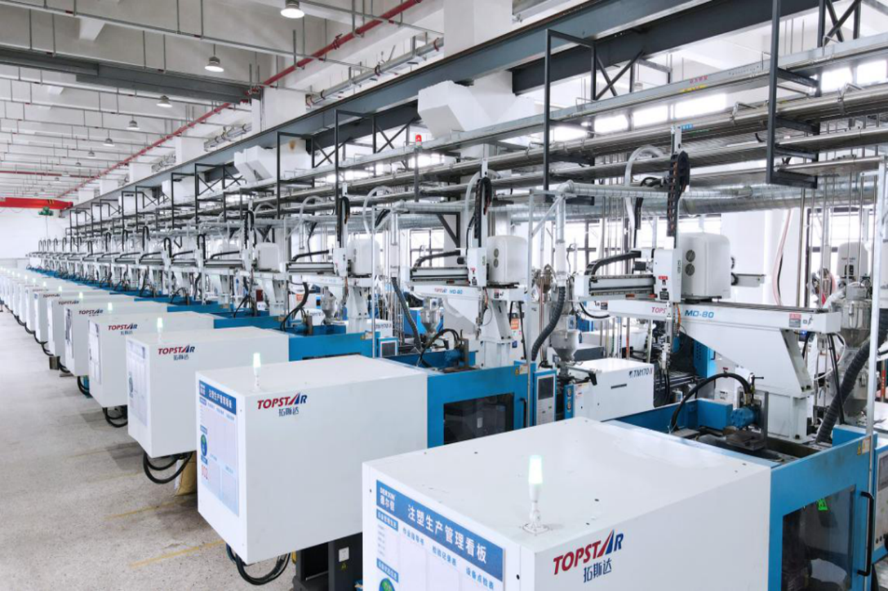
When we deploy multiple injection moulding equipment in a customer’s factory, we’re not just planning the layout; we’re building a manufacturing ecosystem. Good planning translates floor space into predictable output, repeatable quality, and manageable costs. Consider a medium-sized injection moulding plant with ten injection moulding machines and a target monthly production volume of 500,000 parts. With an average cycle time of 20-30 seconds and an average cavity count of four, the layout must support continuous production, fast material flow, robust utilities, easy maintenance, and integrated process control.
To this end, our design utilises cells grouped by product family, each connected to a centralised material supply, mould temperature controller, and a distributed control backbone connected to the MES. This creates a scalable and reliable platform, rather than a collection of ad hoc equipment.
Planning Injection Moulding Equipment for Efficiency
Before planning the layout, engineers conduct a site assessment to translate production targets into space requirements. First, they perform a cycle time calculation. For example, they can use a monthly output of 500,000 parts in 22 16-hour production days to derive hourly requirements, which in turn determine the cell size and number of machines. Next, plan the shop floor structure, designing linear lines for high-volume single-part production, U-shaped cells for flexible moulding-to-post-processing cycles, or island clusters for product mix agility. Ensure that each injection moulding cell maintains a minimum clearance of 2.0 to 2.5 meters for mould changes or robot reach, while also providing a 0.6 to 1.0 meter service corridor behind the injection moulding equipment for utilities and maintenance.
Additionally, locate quality inspection and packaging near the moulding cells to minimise internal transfer time. Plan logistics routes so that raw material receiving, storage, drying, and central conveying are located upstream of the cells, and finished products are located downstream, minimising cross-flow. Finally, plan for future expansion by maintaining a continuous floor space and utilising modular utility taps, which allow for the addition of machines or automated cells with minimal disruption.
Determining Utilities, Power, and Environmental Systems
We accurately estimate the power requirements for electricity, compressed air, chillers, and material dryers by summing peak loads rather than averaging them. For example, a 1,500-2,500 kN injection moulding machine might consume 20-50 kW of peak power during moulding and 2-5 kW at idle. Ten such injection moulding machines require 200-400 kW of peak power, plus a 25-30% margin to accommodate surges and future growth. Therefore, the layout provides three-phase power distribution with local motor starters, surge protectors, and dedicated grounding to reduce electrical noise. Engineers plan centralized compressor units and dryers to maintain the dew point of sensitive plastics below -20°C.
Also, 20% of backup power is reserved. For thermal control, Topstar calculates chiller capacity based on machine heat dissipation and allows for N+1 redundancy. Engineers plan centralized compressor units and dryers to maintain the dew point of sensitive plastics below -20°C.
Ensuring a Continuous Supply to Injection Moulding Equipment
Centralised resin storage and drying systems can significantly reduce contamination, moisture-related defects, and labour costs. For factories with multiple injection moulding equipments, a central material management system is implemented, equipped with automatic feeders, vacuum conveying, and a desiccant or dehumidifying dryer sized according to total melt demand. Furthermore, engineers place color change and dosing stations for compound or additive mixing near specific units, and they arrange conveying lines with quick-disconnect devices to enhance flexibility. They also use moisture and contamination testing devices to define areas for receiving and isolating new materials, and they position auxiliary equipment (re-crushers, pelletizers, scrap collection devices) to minimize cross-traffic and dust. Properly designed material flow reduces cycle scrap, shortens mould change downtime, and improves first-pass yields.
Layout of Surrounding Automation, Robotics, and Auxiliary Equipment
Automation can reduce cycle-to-cycle variability and labour costs, but requires space and control planning. When placing injection moulding equipment, we allocate space for the injection moulding machine’s robots and ensure unobstructed part paths to conveyors, vision inspection systems, or pick-and-place points. Engineers group peripheral equipment, such as pelletizers, mold temperature controllers, dryers, and chillers, to consolidate standard service and maintenance tasks. For high-volume production lines, they design inline automation to incorporate stacking molds with stacking conveyors, rotary indexing devices for multi-shot or multi-stage processes, and robotic parts handling for direct packaging. Furthermore, for sensitive and precision products, they incorporate safety zones, light curtains, and interlocks into the cell layout.
Integrating MES as the Backbone of Digital Control
In modern injection moulding plant layouts, control systems are integrated into a central MES system, enabling the entire fleet of injection moulding equipment to operate collaboratively as a coordinated production asset. Engineers employ distributed control, where each injection molding machine uses a unified control language for real-time motion and safety functions, and it communicates with higher-level systems via Industrial Ethernet or fieldbus. This distributed approach reduces wiring time, minimises latency for time-critical tasks, and simplifies troubleshooting. Under this unified control system, the MES coordinates production scheduling, OEE monitoring, and traceability, and provides performance metrics back to the planning level. Furthermore, integrated energy management monitors machine-level power consumption, enabling peak shaving and driving cost-saving measures during periods of high electricity prices.
Making factory layouts more intelligent and digital
Designing a factory layout for multiple injection moulding machines is a systemic issue that involves integrating space planning, utility sizing, material flow, automation, and control, all of which are interconnected. Starting with throughput targets and production time calculations, we gradually progress to cell expansion, centralised utilities, and distributed control systems. Furthermore, integrating MES and energy management enables operations to optimise output and costs, while also accommodating future expansion through modular utility ports and reserved space.
TRENDING POSTS
- CHINAPLAS 2026 is Coming Soon! 2025/08/18
- New Year, New Beginnings: Topstar Robotics Delivers Heartfelt Service to Keep Customers Thriving! 2025/08/18
- TOPSTAR Global Open Day 2025: Humanoid Robot Debuts, Pioneering a New Decade of Intelligent Manufacturing 2025/08/18
- Topstar Showcases TE II Electric Injection Molding Machines at InterPlas Thailand 2025 2025/08/18
HOT TOPIC
- .ervo motor-driven linear robots
- •
- 1.0 guangdong topstar technology co. ltd
- 1.0 topstar china
- 1.0 topstar robot
- 11
- 160℃ mold temperature controller
- 170 ton injection molding machine
- 2
- 21
- 220-ton injection molding machine
- 23
- 260 ton injection molding machine
- 3 axis robot
- 3 axis robots
- 3 in 1 Compact Dehumidifying Dryer
- 3-axis robot
- 3-axis robots
- 39
- 41
- 460T injection molding machine
- 5-axis CNC machine
- 62
- 90 ton injection molding machine
- accuracy
- Air Chillers
- all electric injection molding machine
- all electric injection molding machines
- all-electric injection molding machine
- All-electric injection molding machines
- and overall production quality. Therefore
- AP-RubberPlas
- auto loader
- automated injection molding machine
- Automation changed engineering
- automation of injection molding robots
- automotive parts injection molding
- Auxiliary Equipment
- auxiliary machine
- Bench Injection Molding Machine
- cabinet dryer
- Cabinet dryer manufacturers
- Cabinet dryers
- chiller
- CNC Drilling Machine
- CNC Drilling Machines
- cnc engraving machine manufacturer
- cnc laser cutting machine manufacturer
- CNC machine
- CNC Machine Center
- CNC Machine for Sale
- CNC Machine Manufacturing
- CNC Machine Tool
- CNC machine tool product
- CNC Machining Center
- CNC wood carving machine
- Cooling system
- Cross-Walking Single Axis Servo Cylinder Robot
- Cross-Walking Single-Axis Servo Cylinder Robot
- Cross-Walking Three-Axis/Five-Axis Servo Driven Robot
- cross-walking three-axis/five-axis servo-driven robot
- Dehumidifier Dryer
- Dehumidifying Dryer
- delta parallel robot
- Desktop Injection Molding Machine
- Desktop injection molding machines
- Desktop Molding Machine
- desktop plastic injection machine
- Desktop Plastic Injection Molding Machine
- Digital Transformation
- direct clamp injection molding machine
- Direct clamp injection molding machines
- Dosing & mixing system
- Drilling Centers
- Drying and dehumidification system
- drying and dehumidifying equipment
- Drying and Dehumidifying System
- drying system
- effective and efficient. Cabinet dryers are also used in other industries where large quantities of material need to be dried
- efficient injection molding machine
- elbow hydraulic injection molding machines
- electric injection molding machine
- electric injection molding machines
- energy-efficient injection molding robot
- energy-efficient water chiller
- energy-efficient water chillers
- energy-saving injection molding machine
- etc. Among injection molding robots
- exhibition
- features of CNC machine
- Feeding And Conveying System
- Five Axis Machine Center
- Flexible Production Line
- Fully automatic injection molding machine
- Gathering Topstar
- giant injection molding machine
- GMU-600 5-Axis Machining Center
- Granulating & Recycling System
- granulator machine
- gravimetric blender
- Heavy duty injection molding machine
- High-precision electric molding machines
- high-precision plastic molding machines
- high-speed all electric injection molding machine
- high-speed electric injection molding machine
- High-Speed Packaging Injection Molding
- Honeycomb rotor dehumidifier
- hopper dryer
- Hopper Dryers
- horizontal injection molding machine
- Horizontal Injection Molding Machines
- Horizontal Injection Moulding Machine
- Horizontal Mixer manufacturer
- How The CNC Machine Works
- hybrid injection molding machine
- hydraulic injection molding machine
- Hydraulic Injection Molding Machines
- in this article
- Industrial AI
- Industrial Automation
- Industrial robot
- Industrial Robot Chinese brand
- industrial robot parts
- industrial robot supplier
- Industrial robots
- Industry Chain
- Injection Manipulator
- injection manipulator robot
- injection mold machines
- Injection molding
- Injection molding automation
- Injection Molding Automation Solution
- injection molding dryer
- Injection molding equipment
- injection molding hopper dryer
- Injection molding machine
- injection molding machine brand
- Injection Molding Machine Factory
- Injection Molding Machine Manufacture
- Injection molding machine manufacturer
- injection molding machine manufacturers
- Injection molding machine procurement
- injection molding machine robotic arm
- injection molding machine with a robot
- Injection molding machines
- injection molding material dehumidifying
- injection molding plant
- injection molding process
- Injection Molding Robot
- injection molding robot arm
- Injection molding robot automation
- Injection molding robotic arm
- injection molding robots
- injection molding whole plant
- injection moulding dryer
- Injection moulding machine
- injection moulding machines
- Injection Moulding Robots
- Injection Robot
- Injection robot arm
- Injection robot manufacturer
- Injection robot wholesale
- injection robots
- Intelligent Factory
- intelligent injection molding machines
- Intelligent Manufacturing
- intelligent mold temperature
- intelligent mold temperature controller
- Intelligent mould temperature controller
- InterPlas Thailand 2025
- Introducing Injection Robot
- It is the best choice for drying large quantities of material at once. Cabinetmakers use these machines because they are fast
- Large flow water type mold temperature controller
- large injection molding machine
- large injection molding machines
- Learn what industrial automation and robotics is
- linear robot
- linear robots
- low speed sound-proof granulator
- machine plastic molding
- make sure to add some! Improvements (2) Keyphrase in introduction: Your keyphrase or its synonyms appear in the first paragraph of the copy
- manipulator machine
- manufacturing
- Manufacturing Innovation
- medical grade injection molding machines
- Medical Injection Molding
- medical injection molding machine
- medical injection molding machines
- micro injection molding machine
- middle speed granulator
- Mini CNC machine manufacturers.
- mobile cover making machine
- Mold Temperature Control System
- mold temperature controller
- mold temperature controllers
- molding machine
- molding material Dehumidifying System
- mould temperature control system
- mould temperature controller
- mould temperature controllers
- New electric injection molding machine
- nitrogen dryer manufacturer
- nitrogen dryer system manufacturer
- Oil type mold temperature controller
- Oil type mold temperature controllers
- open day
- optical component injection molding
- Outbound links: No outbound links appear in this page. Add some! Images: No images appear on this page. Add some! Internal links: No internal links appear in this page
- packaging injection molding
- Packaging Solutions
- PET Preform injection molding
- phone case maker machine
- phone case making machine
- phone cover making machine
- PID Control Mold Temperature Controller
- plastic auto loader
- plastic bottle making machine
- plastic bottle manufacturing
- plastic bucket making machine
- plastic bucket manufacturing
- Plastic chair making machine
- plastic dryer for injection molding
- plastic forming equipment
- Plastic Granulators
- plastic hopper dryer
- plastic injection machine
- plastic injection machines
- plastic injection molding
- Plastic injection molding equipment
- Plastic injection molding machine
- Plastic Injection Molding Machines
- plastic injection moulding machine
- plastic injection moulding machines
- plastic injection robot
- plastic molding
- Plastic Molding Industry
- Plastic Molding machine
- plastic molding machine 1
- Plastic Molding Machines
- plastic molding press
- plastic moulding machine
- plastic phone case making machine
- plastic-molding machine
- powerful granulator
- Powerful Type Sound-Proof Granulator
- precision injection molding
- precision injection molding machines
- production of plastic seats
- pure water mould temperature controller
- Robot injection molding
- robot injection molding machine
- robot manufacturing companies
- Robotic arm for injection molding machine
- robotic injection molding machines
- robotics in injection molding
- SCARA robot
- SCARA robots
- Screw dosers
- Service-oriented manufacturing
- Servo Cylinder Robot
- servo driven robot
- Servo Driven Robots
- servo injection molding machine
- servo injection robots
- servo motor-driven linear robots
- servo-driven 3-axis robot
- Servo-driven injection molding machine
- Servo-Driven Robot
- Setup of injection machine
- Silicone Injection Molding Machine
- six-axis industrial robot
- Smart Manufacturing
- soundproof granulator
- Sprue Picker
- Stainless Hopper Dryer
- Stainless Hopper Dryers
- star club
- swing arm robot
- take-out robot
- take-out robots
- Thailand 4.0
- the choice between servo-driven robots and hydraulic robots will have a certain impact on efficiency
- the most popular injection molding machine
- the type of injection molding robot
- TIC2000 Control System
- TMII injection molding machine
- toggle clamp injection molding machine
- Toggle Hydraulic Injection Molding Machines
- toggle injection molding machine
- Top 10 brands of injection robots
- Topstar
- Topstar Electric Injection Molding Machine InterPlas Thailand 2025 Smart Manufacturing Thailand 4.0
- Topstar Engineering
- Topstar Industrial Robots
- Topstar injection molding intelligent
- Topstar Scara Robots
- Useful Injection molding machine
- Vertical machining centers
- volumetric type blender
- water chiller
- water chillers
- water distributor
- water type mold temperature controller
- Water Type MoldTemperature Controller
- Water-Type Mould Temperature Controllers
- We often face choices when performing injection molding. We will choose the type of injection molding machine
- wholesale of injection molding machines
- x carve CNC
- 热门查询 点击次数 展示 排名 topstar