Injection molding cycle profile optimization: pressure, hold and cooling steps
2025/09/26 By le zhan
Injection molding cycle profile optimization, specifically the coordinated control of pressure, holding, and cooling steps, is the most effective tool for production engineers to improve part quality, reduce cycle time, and lower unit cost. Whether you operate a single-unit injection molding line or manage multiple injection molding machines in a single molding facility, optimizing the cycle profile can deliver significant benefits: fewer sink marks, lower warpage, higher first-pass yields, reduced scrap rates, and shorter ramp-up times after changeovers. An optimized cycle profile can improve profitability while maintaining product performance.
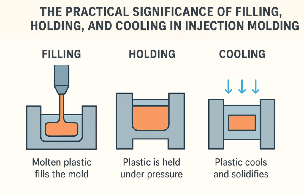
The Practical Significance of Filling, Holding, and Cooling in Injection Molding
Before making adjustments, you must clearly define the actual role of each cycle step on the injection molding machine. The injection molding cycle consists of three interrelated phases: rapid filling, holding, and cooling. The settings for each phase are interdependent, and changing one setting requires revalidating the others.
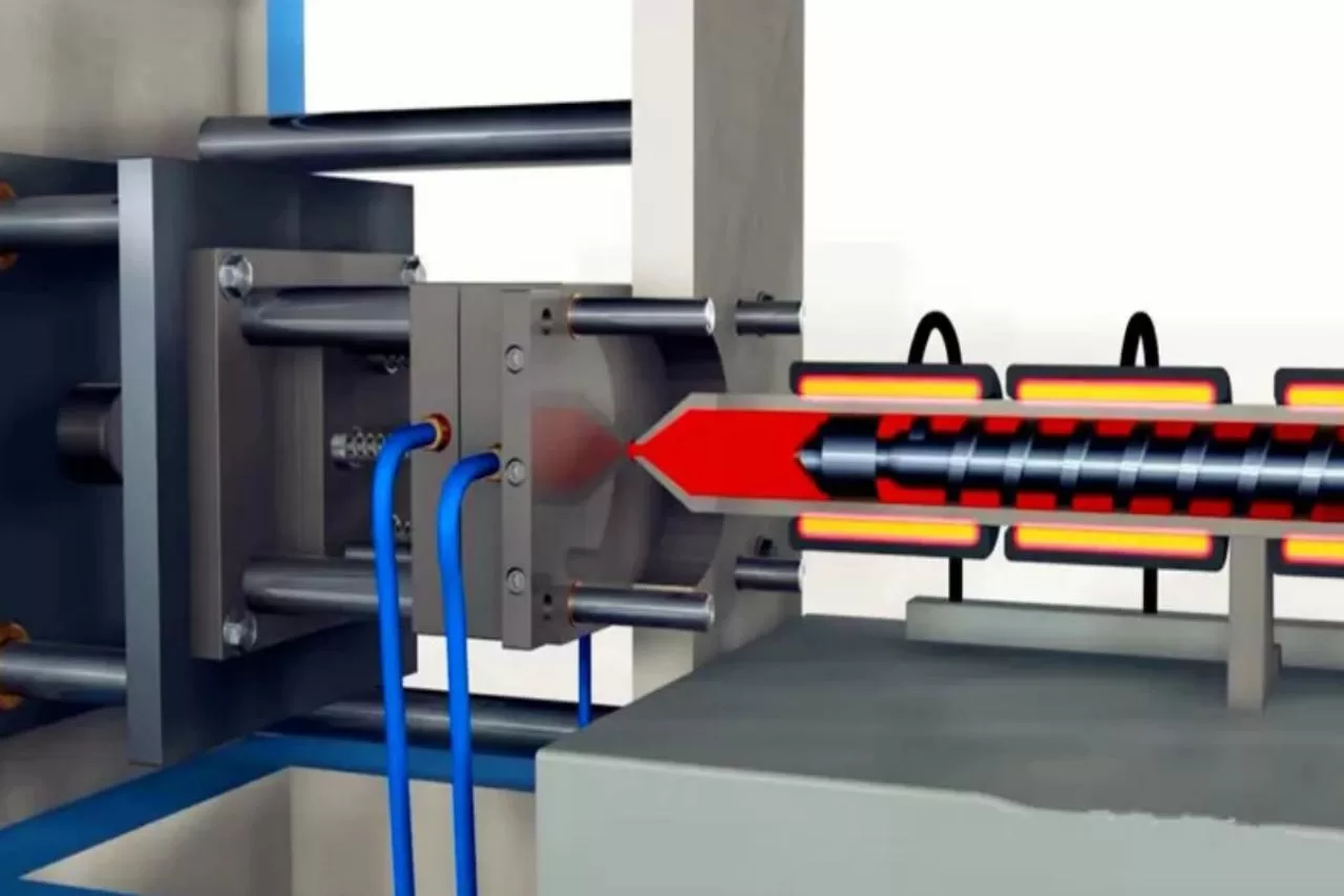
During the filling process, the melt flows from the barrel/nozzle into the runners and cavity. The injection profile determines the fill front velocity, shear heating, and initial direction. Using S-curve acceleration can reduce shear peaks and maintain the progression of the laminar flow front. On many injection molding machines, it is recommended to configure multi-segment velocity profiles to manage long flow lengths or thin ribs. Monitor injection pressure at the nozzle and cavity pressure to detect front lag or excessive packing. The typical goal is to achieve rapid filling, minimizing packing time while avoiding ejection and air entrapment.
Once the cavity is substantially complete, packing compensates for volumetric shrinkage as the part cools. Adequate packing reduces shrinkage and voids, but overpacking can lead to flash and internal stresses. You can switch from velocity control to pressure control at the calibration point to initiate the packing process. After packing, the clamps remain closed until the part cools, which is typically the longest portion of the cycle. Cooling must remove sufficient heat to achieve ejection stiffness. Cooling time depends on the thermal properties of the polymer, part thickness, mold temperature, and the effectiveness of conformal/internal cooling channels. Optimize cooling by balancing mold temperature and cooling time to achieve optimal results.
Analysis of Pressure Control in Injection Molding
Pressure is the primary control variable in injection molding because it transmits force to the melt front and subsequently holds the part in place. Effective pressure profile control means controlling injection pressure during filling and then applying a measured packing/holding pressure strategy that matches the part’s gating and cooling behavior.
During filling, initially set the mode to velocity control to prevent sudden pressure spikes and maintain control over shear and orientation. Switch to pressure control at a point determined by cavity pressure or injection position. Avoid switching position alone, as changes in material viscosity or mold temperature can lead to over- or under-packing. When purchasing an injection molding machine today, select a controller that supports pressure-based switching and features a near-real-time cavity pressure loop.
Use a stepped packing profile with a high initial packing pressure to push the melt into the edge area, followed by a reduced packing pressure to maintain volume compensation as the gate freezes. This reduces internal stress and flash. A typical approach is as follows: Pack 1 = approximately 90-95% of the maximum pressure for a short period; Pack 2 = 60-70% of the remaining pressure. Calibrate the packing duration using the cavity pressure profile. Furthermore, overpressure should be avoided; pressure alone cannot replace a properly designed gate.
Gate Freeze Logic, Time, and Pressure Control for Packing Optimization
Packing is a delicate balance. It can compensate for volumetric shrinkage, but if misused, it can become a source of sink marks, internal stresses, and dimensional drift. Determine the gate freeze point through simple experiments. Maintain a constant packing pressure and record the increase in cavity pressure and part weight as the packing time increases. When the gate freezes, the weight reaches a steady state. This steady state is used as the minimum required packing time, plus a safety margin to account for variations in the process.
This is still common in the absence of sensors. Use injection monitoring to record the time of gate freeze and set the packing time to 80% to 120% of the observed time, taking into account process variations. For conservative production, choose the upper end of the range to avoid underpacking. However, longer packing times increase cycle time and cost. During this process, you need to set an initial packing pressure and then gradually reduce it to maintain the packing pressure as the cavity cools. Implement a decaying pack to reduce internal stress concentrations: initially apply a high-pressure pulse and then gradually reduce the set value until the gate solidifies. This technique typically reduces overall packing time because it avoids the extension force required to compensate for a single high-pressure burst.
How is cooling performed?
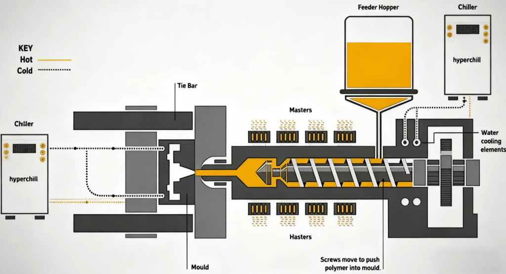
Cooling often dominates cycle time, and intelligent cooling design can reduce ejection time without compromising dimensional stability. Uniform cooling design ensures evenly distributed cooling, eliminating thermal gradients that can cause warpage. Place cooling channels close to thick-walled parts and parallel to the runners for consistent heat dissipation. Where direct cooling is impractical, use baffles and bubblers. For complex geometries, consider conformal cooling to reduce cycle time and hot spots. Integrating a temperature controller ensures a reasonable flow rate and precise, constant temperature control.
For crystalline materials, controlling mold temperature affects crystallinity and shrinkage. For cavities requiring different mold temperatures, separate circuits should be used. Additionally, avoid undersizing water channels, as this can result in insufficient flow. Calculate water channel diameters based on the heat load, use turbulence enhancers where necessary, and ensure that the feed and return manifolds balance the flow to each cavity. Reduce adequate cooling time by improving heat transfer efficiency within material limitations, increasing mold surface contact area, or employing conformal cooling.
Implementing Cycle Optimization Profiles
Optimizing the pressure, packing, and cooling profiles of the injection molding cycle is a technique with clear and measurable benefits. Start by installing instrumentation to collect reliable baseline data, then conduct targeted Design of Experiments (DoEs) to determine the optimal combination of injection speed, packing pressure sequence, and cooling time. Whenever possible, use cavity pressure as the primary signal, as it directly links machine action to part results. When conventional injection molding machines cannot support the required control fidelity, consider upgrading to models from the machine manufacturer that offer closed-loop pressure control, high-frequency data acquisition, and convenient recipe management.
TRENDING POSTS
- CHINAPLAS 2026 is Coming Soon! 2025/09/26
- New Year, New Beginnings: Topstar Robotics Delivers Heartfelt Service to Keep Customers Thriving! 2025/09/26
- TOPSTAR Global Open Day 2025: Humanoid Robot Debuts, Pioneering a New Decade of Intelligent Manufacturing 2025/09/26
- Topstar Showcases TE II Electric Injection Molding Machines at InterPlas Thailand 2025 2025/09/26
HOT TOPIC
- .ervo motor-driven linear robots
- •
- 1.0 guangdong topstar technology co. ltd
- 1.0 topstar china
- 1.0 topstar robot
- 11
- 160℃ mold temperature controller
- 170 ton injection molding machine
- 2
- 21
- 220-ton injection molding machine
- 23
- 260 ton injection molding machine
- 3 axis robot
- 3 axis robots
- 3 in 1 Compact Dehumidifying Dryer
- 3-axis robot
- 3-axis robots
- 39
- 41
- 460T injection molding machine
- 5-axis CNC machine
- 62
- 90 ton injection molding machine
- accuracy
- Air Chillers
- all electric injection molding machine
- all electric injection molding machines
- all-electric injection molding machine
- All-electric injection molding machines
- and overall production quality. Therefore
- AP-RubberPlas
- auto loader
- automated injection molding machine
- Automation changed engineering
- automation of injection molding robots
- automotive parts injection molding
- Auxiliary Equipment
- auxiliary machine
- Bench Injection Molding Machine
- cabinet dryer
- Cabinet dryer manufacturers
- Cabinet dryers
- chiller
- CNC Drilling Machine
- CNC Drilling Machines
- cnc engraving machine manufacturer
- cnc laser cutting machine manufacturer
- CNC machine
- CNC Machine Center
- CNC Machine for Sale
- CNC Machine Manufacturing
- CNC Machine Tool
- CNC machine tool product
- CNC Machining Center
- CNC wood carving machine
- Cooling system
- Cross-Walking Single Axis Servo Cylinder Robot
- Cross-Walking Single-Axis Servo Cylinder Robot
- Cross-Walking Three-Axis/Five-Axis Servo Driven Robot
- cross-walking three-axis/five-axis servo-driven robot
- Dehumidifier Dryer
- Dehumidifying Dryer
- delta parallel robot
- Desktop Injection Molding Machine
- Desktop injection molding machines
- Desktop Molding Machine
- desktop plastic injection machine
- Desktop Plastic Injection Molding Machine
- Digital Transformation
- direct clamp injection molding machine
- Direct clamp injection molding machines
- Dosing & mixing system
- Drilling Centers
- Drying and dehumidification system
- drying and dehumidifying equipment
- Drying and Dehumidifying System
- drying system
- effective and efficient. Cabinet dryers are also used in other industries where large quantities of material need to be dried
- efficient injection molding machine
- elbow hydraulic injection molding machines
- electric injection molding machine
- electric injection molding machines
- energy-efficient injection molding robot
- energy-efficient water chiller
- energy-efficient water chillers
- energy-saving injection molding machine
- etc. Among injection molding robots
- exhibition
- features of CNC machine
- Feeding And Conveying System
- Five Axis Machine Center
- Flexible Production Line
- Fully automatic injection molding machine
- Gathering Topstar
- giant injection molding machine
- GMU-600 5-Axis Machining Center
- Granulating & Recycling System
- granulator machine
- gravimetric blender
- Heavy duty injection molding machine
- High-precision electric molding machines
- high-precision plastic molding machines
- high-speed all electric injection molding machine
- high-speed electric injection molding machine
- High-Speed Packaging Injection Molding
- Honeycomb rotor dehumidifier
- hopper dryer
- Hopper Dryers
- horizontal injection molding machine
- Horizontal Injection Molding Machines
- Horizontal Injection Moulding Machine
- Horizontal Mixer manufacturer
- How The CNC Machine Works
- hybrid injection molding machine
- hydraulic injection molding machine
- Hydraulic Injection Molding Machines
- in this article
- Industrial AI
- Industrial Automation
- Industrial robot
- Industrial Robot Chinese brand
- industrial robot parts
- industrial robot supplier
- Industrial robots
- Industry Chain
- Injection Manipulator
- injection manipulator robot
- injection mold machines
- Injection molding
- Injection molding automation
- Injection Molding Automation Solution
- injection molding dryer
- Injection molding equipment
- injection molding hopper dryer
- Injection molding machine
- injection molding machine brand
- Injection Molding Machine Factory
- Injection Molding Machine Manufacture
- Injection molding machine manufacturer
- injection molding machine manufacturers
- Injection molding machine procurement
- injection molding machine robotic arm
- injection molding machine with a robot
- Injection molding machines
- injection molding material dehumidifying
- injection molding plant
- injection molding process
- Injection Molding Robot
- injection molding robot arm
- Injection molding robot automation
- Injection molding robotic arm
- injection molding robots
- injection molding whole plant
- injection moulding dryer
- Injection moulding machine
- injection moulding machines
- Injection Moulding Robots
- Injection Robot
- Injection robot arm
- Injection robot manufacturer
- Injection robot wholesale
- injection robots
- Intelligent Factory
- intelligent injection molding machines
- Intelligent Manufacturing
- intelligent mold temperature
- intelligent mold temperature controller
- Intelligent mould temperature controller
- InterPlas Thailand 2025
- Introducing Injection Robot
- It is the best choice for drying large quantities of material at once. Cabinetmakers use these machines because they are fast
- Large flow water type mold temperature controller
- large injection molding machine
- large injection molding machines
- Learn what industrial automation and robotics is
- linear robot
- linear robots
- low speed sound-proof granulator
- machine plastic molding
- make sure to add some! Improvements (2) Keyphrase in introduction: Your keyphrase or its synonyms appear in the first paragraph of the copy
- manipulator machine
- manufacturing
- Manufacturing Innovation
- medical grade injection molding machines
- Medical Injection Molding
- medical injection molding machine
- medical injection molding machines
- micro injection molding machine
- middle speed granulator
- Mini CNC machine manufacturers.
- mobile cover making machine
- Mold Temperature Control System
- mold temperature controller
- mold temperature controllers
- molding machine
- molding material Dehumidifying System
- mould temperature control system
- mould temperature controller
- mould temperature controllers
- New electric injection molding machine
- nitrogen dryer manufacturer
- nitrogen dryer system manufacturer
- Oil type mold temperature controller
- Oil type mold temperature controllers
- open day
- optical component injection molding
- Outbound links: No outbound links appear in this page. Add some! Images: No images appear on this page. Add some! Internal links: No internal links appear in this page
- packaging injection molding
- Packaging Solutions
- PET Preform injection molding
- phone case maker machine
- phone case making machine
- phone cover making machine
- PID Control Mold Temperature Controller
- plastic auto loader
- plastic bottle making machine
- plastic bottle manufacturing
- plastic bucket making machine
- plastic bucket manufacturing
- Plastic chair making machine
- plastic dryer for injection molding
- plastic forming equipment
- Plastic Granulators
- plastic hopper dryer
- plastic injection machine
- plastic injection machines
- plastic injection molding
- Plastic injection molding equipment
- Plastic injection molding machine
- Plastic Injection Molding Machines
- plastic injection moulding machine
- plastic injection moulding machines
- plastic injection robot
- plastic molding
- Plastic Molding Industry
- Plastic Molding machine
- plastic molding machine 1
- Plastic Molding Machines
- plastic molding press
- plastic moulding machine
- plastic phone case making machine
- plastic-molding machine
- powerful granulator
- Powerful Type Sound-Proof Granulator
- precision injection molding
- precision injection molding machines
- production of plastic seats
- pure water mould temperature controller
- Robot injection molding
- robot injection molding machine
- robot manufacturing companies
- Robotic arm for injection molding machine
- robotic injection molding machines
- robotics in injection molding
- SCARA robot
- SCARA robots
- Screw dosers
- Service-oriented manufacturing
- Servo Cylinder Robot
- servo driven robot
- Servo Driven Robots
- servo injection molding machine
- servo injection robots
- servo motor-driven linear robots
- servo-driven 3-axis robot
- Servo-driven injection molding machine
- Servo-Driven Robot
- Setup of injection machine
- Silicone Injection Molding Machine
- six-axis industrial robot
- Smart Manufacturing
- soundproof granulator
- Sprue Picker
- Stainless Hopper Dryer
- Stainless Hopper Dryers
- star club
- swing arm robot
- take-out robot
- take-out robots
- Thailand 4.0
- the choice between servo-driven robots and hydraulic robots will have a certain impact on efficiency
- the most popular injection molding machine
- the type of injection molding robot
- TIC2000 Control System
- TMII injection molding machine
- toggle clamp injection molding machine
- Toggle Hydraulic Injection Molding Machines
- toggle injection molding machine
- Top 10 brands of injection robots
- Topstar
- Topstar Electric Injection Molding Machine InterPlas Thailand 2025 Smart Manufacturing Thailand 4.0
- Topstar Engineering
- Topstar Industrial Robots
- Topstar injection molding intelligent
- Topstar Scara Robots
- Useful Injection molding machine
- Vertical machining centers
- volumetric type blender
- water chiller
- water chillers
- water distributor
- water type mold temperature controller
- Water Type MoldTemperature Controller
- Water-Type Mould Temperature Controllers
- We often face choices when performing injection molding. We will choose the type of injection molding machine
- wholesale of injection molding machines
- x carve CNC
- 热门查询 点击次数 展示 排名 topstar