Tips for checking wear of rack and pinion of injection robot?
2025/06/07 By Topstar
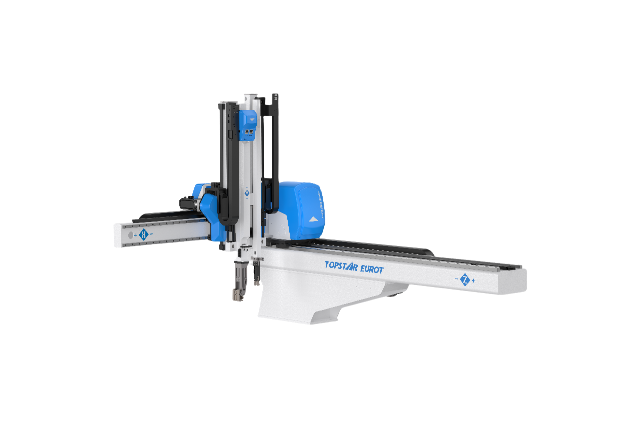
Injection robot that are calibrated before injection molding production can ensure fast and repeatable part pick and placement. The core of one of them is the rack-and-pinion transmission mechanism. However, over time, the continuous meshing between the rack teeth and the pinion will cause metal fatigue, pitting and dimensional wear. Therefore, rack and pinion wear inspection is required before production or during maintenance to ensure positioning accuracy, extend equipment life and reduce unplanned downtime.
Visual observation of the rack wear of the injection robot
Visual inspection is the first line of defense against excessive wear on the rack of the injection robot. After cleaning, use a high-intensity flashlight and a 10x magnifying glass or an endoscope to inspect each tooth on the rack. Look for pitting (and rounded teeth, which indicate material loss. Also, check for discoloration or burnt lubricant, which are signs of excessive friction. For these linear robots, wear is often concentrated at the travel limits where the carriage decelerates, so pay special attention to these end areas. Also, check the rack mounts for loose fasteners or misalignment, as even the slightest misalignment can cause uneven wear patterns to accelerate.
In observation, if you find that pitting or rounding exceeds 1/4 of the tooth face width (10%) or discover deep gouges, you may need to refurbish or replace the rack. Addressing these signs promptly helps prevent shock loads from damaging the internal gearbox and bearings, thereby maintaining the servo motor’s efficiency.
Dimensional Measurements for Backlash Monitoring
In addition to visual cues, quantifying backlash can indicate wear. Mount a magnetic base dial indicator to the robot carriage and place its stylus against a flat machined surface adjacent to the rack. With the injection robot in manual jog mode and holding torque disabled, gently reverse the drive direction while watching the indicator. The travel measured before the carriage begins to move is the backlash of the system. For injection robots, the acceptable backlash range is 0.05 mm to 0.15 mm. You can detect uneven wear by recording the backlash value at multiple points along the rack’s travel. If the measured value continuously exceeds the maximum tolerance, you can adjust the preload of the pinion bearing or schedule the replacement of the rack or pinion.
Inspect and lubricate the pinion of the injection robot
The pinion of the injection robot is also susceptible to wear. After removing the protective cover, rotate the pinion of the injection robot by hand and inspect each tooth under a magnifying glass. Check for wear, micro-cracks at the root fillet, or uneven wear. Additionally, inspect the pinion mounting hole for signs of fretting wear or keyway deformation, which may cause the gear to slip. Worn-bearing seals can allow contaminants to penetrate; therefore, inspect adjacent seals and replace them if you find them hardened or cracked.
Proper lubrication can prevent the cornerstone of wear. Use a precision grease gun equipped with a flexible hose to apply a thin, even layer of grease to the gear meshing area for targeted delivery. However, we must avoid over-lubrication, which can accumulate debris and increase operating temperatures. For 3-axis robots operating in highly contaminated injection molding production environments, consider every 200-300 hours To clean the gear mesh and relubricate to minimize friction, keep out moisture, and extend the life of the rack and pinion.
Alignment Verification and Correction
Misalignment between the rack and pinion accelerates wear and degrades performance. To verify the alignment of the injection molding robot, use a precision ruler or laser alignment tool. Place the ruler along the linear path of the rack and slowly move the pinion. Any visible play or sticking points indicate a parallelism error. For angular misalignment, mount a dial indicator on the pinion shaft and rotate the gear to check if the runout exceeds 0.02 mm. On injection molding robots, guide misalignment is often accompanied by rack misalignment, requiring confirmation of parallelism between the rack shaft and linear guide-bearing surfaces.
If misalignment is detected, realign by adjusting the rack mounting slot. Loosen, reposition, and retighten the anchor bolts while monitoring the indicator readings. For pinion runout, replace worn bearings or adjust the shaft seats as needed. After making the necessary alignment adjustments, relubricate the gear mesh and recheck the backlash.
Perform overall maintenance regularly
As important as a stand-alone rack and pinion inspection procedure is, incorporating it into a comprehensive injection robot maintenance program will multiply its benefits. Combining rack and pinion inspections with servo drive diagnostics, linear guide lubrication, and mold temperature controller maintenance can optimize downtime windows. Additionally, monitor environmental conditions and perform routine maintenance after completing mold remediation. Schedule a gear inspection immediately after the robot shows signs of wear.
Leverage data from the robot control software as an indicator that gear wear may be increasing. By correlating mechanical wear data with operational analytics, operators can adopt a predictive maintenance approach to improve the reliability of injection molding robots by replacing components based on usage patterns rather than fixed schedules.
Perform regular inspections and maintenance for smooth operation
Performing regular inspections and maintenance on the rack and pinion drive system of an injection robot can help maintain high precision, prevent unexpected downtime, and ensure part quality. Consistent performance of the injection robot can be ensured by combining comprehensive visual inspections, precise backlash measurements, and targeted lubrication measures. Integrating these techniques into a broader preventive and predictive maintenance framework can lead to operational excellence, ensuring the smooth operation of high-speed production lines.
TRENDING POSTS
- TOPSTAR Global Open Day 2025: Humanoid Robot Debuts, Pioneering a New Decade of Intelligent Manufacturing 2025/06/07
- Topstar Showcases TE II Electric Injection Molding Machines at InterPlas Thailand 2025 2025/06/07
- Topstar Expands Its Ecosystem Partnerships to Drive Smart Manufacturing Innovation 2025/06/07
- What factors can cause delays in the injection molding process of plastic molding machine? 2025/06/07
HOT TOPIC
- .ervo motor-driven linear robots
- •
- 1.0 guangdong topstar technology co. ltd
- 1.0 topstar china
- 1.0 topstar robot
- 11
- 160℃ mold temperature controller
- 170 ton injection molding machine
- 2
- 21
- 220-ton injection molding machine
- 23
- 260 ton injection molding machine
- 3 axis robot
- 3 axis robots
- 3 in 1 Compact Dehumidifying Dryer
- 3-axis robot
- 3-axis robots
- 39
- 41
- 460T injection molding machine
- 5-axis CNC machine
- 62
- 90 ton injection molding machine
- accuracy
- Air Chillers
- all electric injection molding machine
- all electric injection molding machines
- all-electric injection molding machine
- All-electric injection molding machines
- and overall production quality. Therefore
- AP-RubberPlas
- auto loader
- automated injection molding machine
- Automation changed engineering
- automation of injection molding robots
- automotive parts injection molding
- Auxiliary Equipment
- auxiliary machine
- Bench Injection Molding Machine
- cabinet dryer
- Cabinet dryer manufacturers
- Cabinet dryers
- chiller
- CNC Drilling Machine
- CNC Drilling Machines
- cnc engraving machine manufacturer
- cnc laser cutting machine manufacturer
- CNC machine
- CNC Machine Center
- CNC Machine for Sale
- CNC Machine Manufacturing
- CNC Machine Tool
- CNC machine tool product
- CNC Machining Center
- CNC wood carving machine
- Cooling system
- Cross-Walking Single Axis Servo Cylinder Robot
- Cross-Walking Single-Axis Servo Cylinder Robot
- Cross-Walking Three-Axis/Five-Axis Servo Driven Robot
- cross-walking three-axis/five-axis servo-driven robot
- Dehumidifier Dryer
- Dehumidifying Dryer
- delta parallel robot
- Desktop Injection Molding Machine
- Desktop injection molding machines
- Desktop Molding Machine
- desktop plastic injection machine
- Desktop Plastic Injection Molding Machine
- Digital Transformation
- direct clamp injection molding machine
- Direct clamp injection molding machines
- Dosing & mixing system
- Drilling Centers
- Drying and dehumidification system
- drying and dehumidifying equipment
- Drying and Dehumidifying System
- drying system
- effective and efficient. Cabinet dryers are also used in other industries where large quantities of material need to be dried
- efficient injection molding machine
- elbow hydraulic injection molding machines
- electric injection molding machine
- electric injection molding machines
- energy-efficient injection molding robot
- energy-efficient water chiller
- energy-efficient water chillers
- energy-saving injection molding machine
- etc. Among injection molding robots
- exhibition
- features of CNC machine
- Feeding And Conveying System
- Five Axis Machine Center
- Flexible Production Line
- Fully automatic injection molding machine
- Gathering Topstar
- giant injection molding machine
- GMU-600 5-Axis Machining Center
- Granulating & Recycling System
- granulator machine
- gravimetric blender
- Heavy duty injection molding machine
- High-precision electric molding machines
- high-precision plastic molding machines
- high-speed all electric injection molding machine
- high-speed electric injection molding machine
- High-Speed Packaging Injection Molding
- Honeycomb rotor dehumidifier
- hopper dryer
- Hopper Dryers
- horizontal injection molding machine
- Horizontal Injection Molding Machines
- Horizontal Injection Moulding Machine
- Horizontal Mixer manufacturer
- How The CNC Machine Works
- hybrid injection molding machine
- hydraulic injection molding machine
- Hydraulic Injection Molding Machines
- in this article
- Industrial AI
- Industrial Automation
- Industrial robot
- Industrial Robot Chinese brand
- industrial robot parts
- industrial robot supplier
- Industrial robots
- Industry Chain
- Injection Manipulator
- injection manipulator robot
- injection mold machines
- Injection molding
- Injection molding automation
- Injection Molding Automation Solution
- injection molding dryer
- Injection molding equipment
- injection molding hopper dryer
- Injection molding machine
- injection molding machine brand
- Injection Molding Machine Factory
- Injection Molding Machine Manufacture
- Injection molding machine manufacturer
- injection molding machine manufacturers
- Injection molding machine procurement
- injection molding machine robotic arm
- injection molding machine with a robot
- Injection molding machines
- injection molding material dehumidifying
- injection molding plant
- injection molding process
- Injection Molding Robot
- injection molding robot arm
- Injection molding robot automation
- Injection molding robotic arm
- injection molding robots
- injection moulding dryer
- Injection moulding machine
- injection moulding machines
- Injection Moulding Robots
- Injection Robot
- Injection robot arm
- Injection robot manufacturer
- Injection robot wholesale
- injection robots
- Intelligent Factory
- intelligent injection molding machines
- Intelligent Manufacturing
- intelligent mold temperature
- intelligent mold temperature controller
- Intelligent mould temperature controller
- InterPlas Thailand 2025
- Introducing Injection Robot
- It is the best choice for drying large quantities of material at once. Cabinetmakers use these machines because they are fast
- Large flow water type mold temperature controller
- large injection molding machine
- large injection molding machines
- Learn what industrial automation and robotics is
- linear robot
- linear robots
- low speed sound-proof granulator
- machine plastic molding
- make sure to add some! Improvements (2) Keyphrase in introduction: Your keyphrase or its synonyms appear in the first paragraph of the copy
- manipulator machine
- manufacturing
- Manufacturing Innovation
- medical grade injection molding machines
- Medical Injection Molding
- medical injection molding machine
- medical injection molding machines
- micro injection molding machine
- middle speed granulator
- Mini CNC machine manufacturers.
- mobile cover making machine
- Mold Temperature Control System
- mold temperature controller
- mold temperature controllers
- molding machine
- molding material Dehumidifying System
- mould temperature control system
- mould temperature controller
- mould temperature controllers
- New electric injection molding machine
- nitrogen dryer manufacturer
- nitrogen dryer system manufacturer
- Oil type mold temperature controller
- Oil type mold temperature controllers
- open day
- optical component injection molding
- Outbound links: No outbound links appear in this page. Add some! Images: No images appear on this page. Add some! Internal links: No internal links appear in this page
- packaging injection molding
- Packaging Solutions
- PET Preform injection molding
- phone case maker machine
- phone case making machine
- phone cover making machine
- PID Control Mold Temperature Controller
- plastic auto loader
- plastic bottle making machine
- plastic bottle manufacturing
- plastic bucket making machine
- plastic bucket manufacturing
- Plastic chair making machine
- plastic dryer for injection molding
- plastic forming equipment
- Plastic Granulators
- plastic hopper dryer
- plastic injection machine
- plastic injection machines
- plastic injection molding
- Plastic injection molding equipment
- Plastic injection molding machine
- Plastic Injection Molding Machines
- plastic injection moulding machine
- plastic injection moulding machines
- plastic injection robot
- plastic molding
- Plastic Molding Industry
- Plastic Molding machine
- plastic molding machine 1
- Plastic Molding Machines
- plastic molding press
- plastic moulding machine
- plastic phone case making machine
- plastic-molding machine
- powerful granulator
- Powerful Type Sound-Proof Granulator
- precision injection molding
- precision injection molding machines
- production of plastic seats
- pure water mould temperature controller
- Robot injection molding
- robot injection molding machine
- robot manufacturing companies
- Robotic arm for injection molding machine
- robotic injection molding machines
- robotics in injection molding
- SCARA robot
- SCARA robots
- Screw dosers
- Service-oriented manufacturing
- Servo Cylinder Robot
- servo driven robot
- Servo Driven Robots
- servo injection molding machine
- servo injection robots
- servo motor-driven linear robots
- servo-driven 3-axis robot
- Servo-driven injection molding machine
- Servo-Driven Robot
- Setup of injection machine
- Silicone Injection Molding Machine
- six-axis industrial robot
- Smart Manufacturing
- soundproof granulator
- Stainless Hopper Dryer
- Stainless Hopper Dryers
- star club
- swing arm robot
- take-out robot
- take-out robots
- Thailand 4.0
- the choice between servo-driven robots and hydraulic robots will have a certain impact on efficiency
- the most popular injection molding machine
- the type of injection molding robot
- TIC2000 Control System
- TMII injection molding machine
- toggle clamp injection molding machine
- Toggle Hydraulic Injection Molding Machines
- toggle injection molding machine
- Top 10 brands of injection robots
- Topstar
- Topstar Electric Injection Molding Machine InterPlas Thailand 2025 Smart Manufacturing Thailand 4.0
- Topstar Engineering
- Topstar Industrial Robots
- Topstar injection molding intelligent
- Topstar Scara Robots
- Useful Injection molding machine
- Vertical machining centers
- volumetric type blender
- water chiller
- water chillers
- water distributor
- water type mold temperature controller
- Water Type MoldTemperature Controller
- Water-Type Mould Temperature Controllers
- We often face choices when performing injection molding. We will choose the type of injection molding machine
- wholesale of injection molding machines
- x carve CNC
- 热门查询 点击次数 展示 排名 topstar