Troubleshooting Short Shots: Flow and Pressure in the Injection Molding Process
2025/09/15 By le zhan
Short shots, flash, weld lines, and inconsistent part weight—these are symptoms, not the root causes. At the heart of many recurring defects lies the relationship between flow and pressure in the injection molding process. First, we must understand the core facts. First, polymer melts behave differently from water; their viscosity is highly dependent on temperature and shear. Second, injection molding machines are energy-constrained systems. Their screw speed, pump capacity, barrel temperature, and nozzle geometry create a layered hierarchy of constraints that dictate the achievable flow and pressure combinations. Addressing these defects requires proper part design, mold hydraulics, and injection molding machine performance to ensure the melt front fills the cavity before cooling locks in, avoiding excessive pressure at the gate and bottlenecks.
Melt Rheology, Pressure Drop, and Injection Molding Machine Performance in the Injection Molding Process
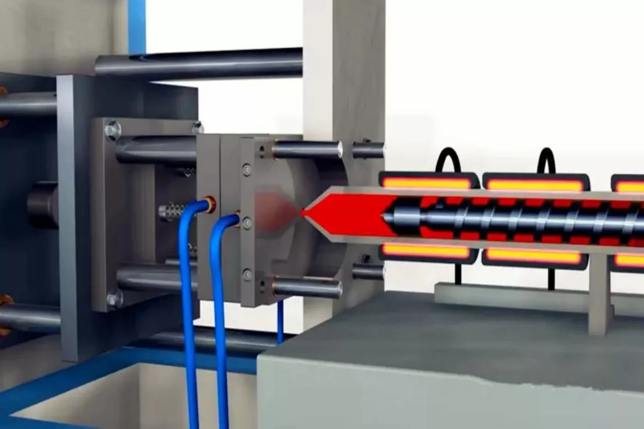
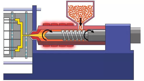
To address defects related to flow and pressure, it’s important to understand the fundamental principles of melt delivery control in the injection molding process. Polymer viscosity is not constant, and many engineering plastics exhibit shear-thinning properties and are highly temperature-sensitive. This means that flow rate, applied shear, and barrel/nozzle temperature form a feedback loop. Increasing injection speed increases shear heating and reduces apparent viscosity, which can improve filling, but may also raise melt temperature and risk degradation.
During pressure drop, the system needs a pressure head capable of overcoming flow resistance to push the melt through runners, gates, and thin walls. In practice, the required injection pressure increases with increasing flow rate and path difficulty. Therefore, designers often use narrow gates, which reduce the instantaneous flow area and thus require higher nozzle pressure.
Injection molding machines typically deliver energy in two ways: volumetric rate and pressure capacity. For hydraulic presses, peak pressure and available flow are determined by pump displacement, drive power, and relief valve settings. For all electric systems, motor torque and screw design limit the achievable pressure at a given speed. Therefore, it’s important to understand the key practical specifications for each injection molding machine in your facility: maximum injection pressure, maximum injection speed or volumetric flow rate, screw/plunger stroke and diameter, and pressure/speed control response time. This data can help you determine whether a short shot is a machine limitation or a molding process issue.
The Impact of Mold and Part Design on the Injection Molding Process
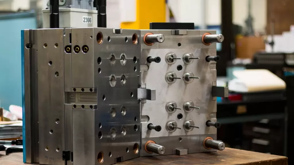
Adjusting gate size, runner layout, venting, and wall thickness is often a quicker and more economical way to address deficiencies than replacing the injection molding machine. In injection molding, each of these design elements directly impacts the required injection pressure and achievable flow rate.
Gate size determines the local shear rate and pressure drop as the melt enters the cavity. A small gate can prevent the injection molding machine from achieving the required flow rate, resulting in slow filling or undershot. Conversely, an oversized gate reduces injection pressure requirements but may result in jetting, weakened weld line strength, or cosmetic issues. For multi-cavity molds, ensure that runner resistance is balanced so that all cavities achieve similar pressures and fill times.
Long runners or thin walls significantly increase pressure requirements. The pressure required to fill long, narrow runners is directly proportional to runner length and inversely proportional to thickness. If a part has thick-to-thin transitions or thin ribs, consider carefully before attempting radical injection molding machine modifications. Furthermore, insufficient venting can cause trapped air to obstruct melt flow. Despite increasing pressure, filling stalls often leads to incomplete filling or burning. Effective venting at weld lines, deep ribs, or corners allows air to escape, reducing the required injection pressure. For these issues, subtle but targeted modifications, such as slightly increasing the gate diameter, shortening the flow length with springback beads, or improving the vent size, can often restore a complete part without significant mold downtime.
Speed-Pressure Curves, Switchover, and Advanced Control
In the injection molding process, determining when to switch from speed control to pressure control and how to adjust the speed and pressure curves is crucial. This decision determines whether the cavity fills, whether holding pressure stabilizes the material, and whether the process minimizes defects. A common practice is to use speed-pressure switching, where operators inject at a specified screw speed until they reach the set injection position or a preset switchover point, and then switch to pressure control for holding pressure.
Of course, many parts benefit from a phased injection process, rather than a single speed. Initially, a strong injection speed is used to fill long runners or gates, followed by a gentler injection speed in the middle to limit shear, and finally, a high pressure in the final stage to compensate for solidification. Similarly, holding pressure can be multi-staged, with peak pressure applied immediately after the switch to the critical holding zone, followed by a gradual reduction in pressure to avoid excessive flash while maintaining dimensional stability.
Furthermore, Topstar’s injection molding machines support adaptive control: real-time feedback from cavity pressure, screw position, and barrel pressure adjusts speed and pressure to keep the process within a defined window. This allows for the conversion of marginally short processes into stable production. In production, the maximum injection speed can be limited to within the acceptable range for the nozzle and gate. Use shot size monitoring and cross-check with cavity pressure to detect short circuits early.
Targeted Fixes for Common Flow and Pressure-Related Defects
In production, defects can occur quickly and require rapid diagnosis. Below are common symptoms you may encounter during injection molding, their causes, and precise corrective measures.
Short shot causes Include Insufficient pressure or flow to fill the mold cavity before the gate freezes, runner blockage, and decreased melt fluidity. Solutions: Increase injection speed and/or injection pressure, moderately increase melt temperature to reduce viscosity, enlarge the gate or smooth the gate entrance, improve venting, and check for nozzle/check valve blockage.
Scorch marks and air pockets: Caused by compression of the melt as it advances through poorly vented areas, resulting in air trapping. Solution: Add or enlarge the vent, reduce injection speed to allow air to escape, and decrease back pressure to promote flow.
Flash: Caused by excessive holding pressure or injection pressure, as well as excessive clamping force loss. Common solutions include reducing holding pressure or holding time, checking clamping force and tie rod alignment, and inspecting the mold seals or ejector bosses for wear.
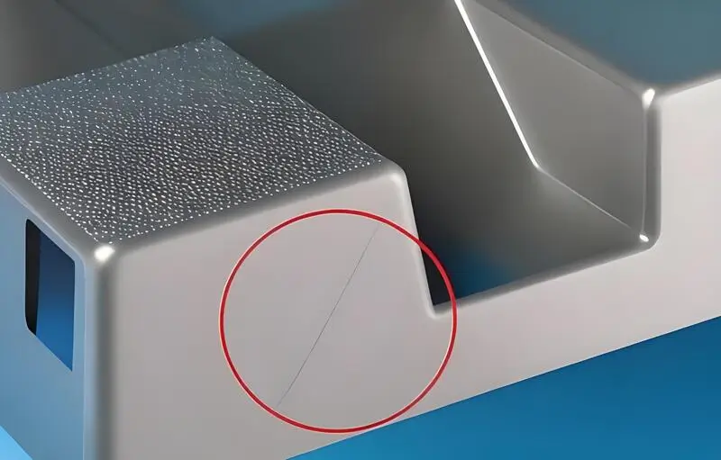
Jet and flow marks: Excessive melt velocity at the gate causes jetting, and the gate geometry may be inappropriate. Solution: Reduce the initial fill speed or reshape the gate to create a laminar inlet.
Causes of weight variation or cycle instability include inconsistent shot weight, screw slippage, compressibility, or outgassing. Check the shot weight control and rezero the scale, inspect the screw head and rings for wear, and calibrate the injection molding machine pump/servo drive.
Troubleshooting and Preventing Flow and Pressure Insufficiency
To address flow and pressure insufficiency in the injection molding process, it’s necessary to instrument the process, systematically test variables, and implement a control strategy that matches the injection molding machine’s capabilities to the mold design. In production, this means collecting baseline data, conducting controlled experiments, varying one variable at a time, prioritizing cavity pressure-based switching and staged speed/pressure profiles over simple fixed-position control, and validating corrective actions through capability studies. This disciplined approach can shorten the time to root cause, prevent recurrence of defects, and safeguard production capabilities.
TRENDING POSTS
- New Year, New Beginnings: Topstar Robotics Delivers Heartfelt Service to Keep Customers Thriving! 2025/09/15
- TOPSTAR Global Open Day 2025: Humanoid Robot Debuts, Pioneering a New Decade of Intelligent Manufacturing 2025/09/15
- Topstar Showcases TE II Electric Injection Molding Machines at InterPlas Thailand 2025 2025/09/15
- Topstar Expands Its Ecosystem Partnerships to Drive Smart Manufacturing Innovation 2025/09/15
HOT TOPIC
- .ervo motor-driven linear robots
- •
- 1.0 guangdong topstar technology co. ltd
- 1.0 topstar china
- 1.0 topstar robot
- 11
- 160℃ mold temperature controller
- 170 ton injection molding machine
- 2
- 21
- 220-ton injection molding machine
- 23
- 260 ton injection molding machine
- 3 axis robot
- 3 axis robots
- 3 in 1 Compact Dehumidifying Dryer
- 3-axis robot
- 3-axis robots
- 39
- 41
- 460T injection molding machine
- 5-axis CNC machine
- 62
- 90 ton injection molding machine
- accuracy
- Air Chillers
- all electric injection molding machine
- all electric injection molding machines
- all-electric injection molding machine
- All-electric injection molding machines
- and overall production quality. Therefore
- AP-RubberPlas
- auto loader
- automated injection molding machine
- Automation changed engineering
- automation of injection molding robots
- automotive parts injection molding
- Auxiliary Equipment
- auxiliary machine
- Bench Injection Molding Machine
- cabinet dryer
- Cabinet dryer manufacturers
- Cabinet dryers
- chiller
- CNC Drilling Machine
- CNC Drilling Machines
- cnc engraving machine manufacturer
- cnc laser cutting machine manufacturer
- CNC machine
- CNC Machine Center
- CNC Machine for Sale
- CNC Machine Manufacturing
- CNC Machine Tool
- CNC machine tool product
- CNC Machining Center
- CNC wood carving machine
- Cooling system
- Cross-Walking Single Axis Servo Cylinder Robot
- Cross-Walking Single-Axis Servo Cylinder Robot
- Cross-Walking Three-Axis/Five-Axis Servo Driven Robot
- cross-walking three-axis/five-axis servo-driven robot
- Dehumidifier Dryer
- Dehumidifying Dryer
- delta parallel robot
- Desktop Injection Molding Machine
- Desktop injection molding machines
- Desktop Molding Machine
- desktop plastic injection machine
- Desktop Plastic Injection Molding Machine
- Digital Transformation
- direct clamp injection molding machine
- Direct clamp injection molding machines
- Dosing & mixing system
- Drilling Centers
- Drying and dehumidification system
- drying and dehumidifying equipment
- Drying and Dehumidifying System
- drying system
- effective and efficient. Cabinet dryers are also used in other industries where large quantities of material need to be dried
- efficient injection molding machine
- elbow hydraulic injection molding machines
- electric injection molding machine
- electric injection molding machines
- energy-efficient injection molding robot
- energy-efficient water chiller
- energy-efficient water chillers
- energy-saving injection molding machine
- etc. Among injection molding robots
- exhibition
- features of CNC machine
- Feeding And Conveying System
- Five Axis Machine Center
- Flexible Production Line
- Fully automatic injection molding machine
- Gathering Topstar
- giant injection molding machine
- GMU-600 5-Axis Machining Center
- Granulating & Recycling System
- granulator machine
- gravimetric blender
- Heavy duty injection molding machine
- High-precision electric molding machines
- high-precision plastic molding machines
- high-speed all electric injection molding machine
- high-speed electric injection molding machine
- High-Speed Packaging Injection Molding
- Honeycomb rotor dehumidifier
- hopper dryer
- Hopper Dryers
- horizontal injection molding machine
- Horizontal Injection Molding Machines
- Horizontal Injection Moulding Machine
- Horizontal Mixer manufacturer
- How The CNC Machine Works
- hybrid injection molding machine
- hydraulic injection molding machine
- Hydraulic Injection Molding Machines
- in this article
- Industrial AI
- Industrial Automation
- Industrial robot
- Industrial Robot Chinese brand
- industrial robot parts
- industrial robot supplier
- Industrial robots
- Industry Chain
- Injection Manipulator
- injection manipulator robot
- injection mold machines
- Injection molding
- Injection molding automation
- Injection Molding Automation Solution
- injection molding dryer
- Injection molding equipment
- injection molding hopper dryer
- Injection molding machine
- injection molding machine brand
- Injection Molding Machine Factory
- Injection Molding Machine Manufacture
- Injection molding machine manufacturer
- injection molding machine manufacturers
- Injection molding machine procurement
- injection molding machine robotic arm
- injection molding machine with a robot
- Injection molding machines
- injection molding material dehumidifying
- injection molding plant
- injection molding process
- Injection Molding Robot
- injection molding robot arm
- Injection molding robot automation
- Injection molding robotic arm
- injection molding robots
- injection moulding dryer
- Injection moulding machine
- injection moulding machines
- Injection Moulding Robots
- Injection Robot
- Injection robot arm
- Injection robot manufacturer
- Injection robot wholesale
- injection robots
- Intelligent Factory
- intelligent injection molding machines
- Intelligent Manufacturing
- intelligent mold temperature
- intelligent mold temperature controller
- Intelligent mould temperature controller
- InterPlas Thailand 2025
- Introducing Injection Robot
- It is the best choice for drying large quantities of material at once. Cabinetmakers use these machines because they are fast
- Large flow water type mold temperature controller
- large injection molding machine
- large injection molding machines
- Learn what industrial automation and robotics is
- linear robot
- linear robots
- low speed sound-proof granulator
- machine plastic molding
- make sure to add some! Improvements (2) Keyphrase in introduction: Your keyphrase or its synonyms appear in the first paragraph of the copy
- manipulator machine
- manufacturing
- Manufacturing Innovation
- medical grade injection molding machines
- Medical Injection Molding
- medical injection molding machine
- medical injection molding machines
- micro injection molding machine
- middle speed granulator
- Mini CNC machine manufacturers.
- mobile cover making machine
- Mold Temperature Control System
- mold temperature controller
- mold temperature controllers
- molding machine
- molding material Dehumidifying System
- mould temperature control system
- mould temperature controller
- mould temperature controllers
- New electric injection molding machine
- nitrogen dryer manufacturer
- nitrogen dryer system manufacturer
- Oil type mold temperature controller
- Oil type mold temperature controllers
- open day
- optical component injection molding
- Outbound links: No outbound links appear in this page. Add some! Images: No images appear on this page. Add some! Internal links: No internal links appear in this page
- packaging injection molding
- Packaging Solutions
- PET Preform injection molding
- phone case maker machine
- phone case making machine
- phone cover making machine
- PID Control Mold Temperature Controller
- plastic auto loader
- plastic bottle making machine
- plastic bottle manufacturing
- plastic bucket making machine
- plastic bucket manufacturing
- Plastic chair making machine
- plastic dryer for injection molding
- plastic forming equipment
- Plastic Granulators
- plastic hopper dryer
- plastic injection machine
- plastic injection machines
- plastic injection molding
- Plastic injection molding equipment
- Plastic injection molding machine
- Plastic Injection Molding Machines
- plastic injection moulding machine
- plastic injection moulding machines
- plastic injection robot
- plastic molding
- Plastic Molding Industry
- Plastic Molding machine
- plastic molding machine 1
- Plastic Molding Machines
- plastic molding press
- plastic moulding machine
- plastic phone case making machine
- plastic-molding machine
- powerful granulator
- Powerful Type Sound-Proof Granulator
- precision injection molding
- precision injection molding machines
- production of plastic seats
- pure water mould temperature controller
- Robot injection molding
- robot injection molding machine
- robot manufacturing companies
- Robotic arm for injection molding machine
- robotic injection molding machines
- robotics in injection molding
- SCARA robot
- SCARA robots
- Screw dosers
- Service-oriented manufacturing
- Servo Cylinder Robot
- servo driven robot
- Servo Driven Robots
- servo injection molding machine
- servo injection robots
- servo motor-driven linear robots
- servo-driven 3-axis robot
- Servo-driven injection molding machine
- Servo-Driven Robot
- Setup of injection machine
- Silicone Injection Molding Machine
- six-axis industrial robot
- Smart Manufacturing
- soundproof granulator
- Sprue Picker
- Stainless Hopper Dryer
- Stainless Hopper Dryers
- star club
- swing arm robot
- take-out robot
- take-out robots
- Thailand 4.0
- the choice between servo-driven robots and hydraulic robots will have a certain impact on efficiency
- the most popular injection molding machine
- the type of injection molding robot
- TIC2000 Control System
- TMII injection molding machine
- toggle clamp injection molding machine
- Toggle Hydraulic Injection Molding Machines
- toggle injection molding machine
- Top 10 brands of injection robots
- Topstar
- Topstar Electric Injection Molding Machine InterPlas Thailand 2025 Smart Manufacturing Thailand 4.0
- Topstar Engineering
- Topstar Industrial Robots
- Topstar injection molding intelligent
- Topstar Scara Robots
- Useful Injection molding machine
- Vertical machining centers
- volumetric type blender
- water chiller
- water chillers
- water distributor
- water type mold temperature controller
- Water Type MoldTemperature Controller
- Water-Type Mould Temperature Controllers
- We often face choices when performing injection molding. We will choose the type of injection molding machine
- wholesale of injection molding machines
- x carve CNC
- 热门查询 点击次数 展示 排名 topstar