Guide to PID control Mold temperature controller: Fix Low-Temperature Dead Zones in Cold Runner Injection Molding
2025/12/10 By le zhan
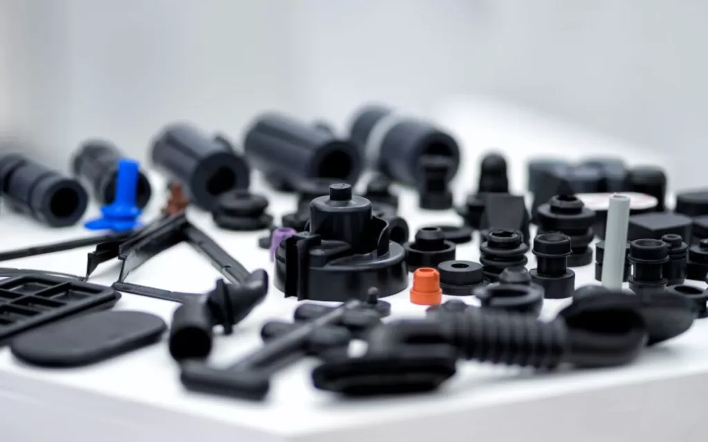
A car interior parts manufacturer was struggling with problems with cold-runner injection molds. Their products suffered from defects such as shrinkage marks, short shots, and uneven wall thickness, all stemming from “low-temperature dead zones” in the runner system, where the temperature is 15-20 degrees Fahrenheit below the set value. Their traditional on/off mold temperature controllers were simply ineffective, often leading to overheating to repair cold spots, followed by overheating and new defects.Topstar’s PID control mold temperature controller effectively solved this problem. Within two weeks of installation, the dead zone disappeared. The scrap rate plummeted to 3%, and the controller reduced energy consumption by 10% by precisely regulating heat output, eliminating waste caused by overheating. Therefore, we will explain in detail how the PID control mold temperature controller eliminates dead zones, improves efficiency by 10%, and ensures temperature stability.
What are low-temperature dead zones in injection molding, and why do they damage parts?
Before addressing low-temperature dead zone problems, you need to understand what they are and why traditional mold temperature controllers cannot handle them. In cold-runner injection molding, the runner is the network of channels that convey molten plastic into the mold cavity. To ensure proper part molding, the runner temperature must be maintained within a strict set temperature range, typically ±1°F. A low-temperature dead zone is an isolated area in the runner that cools below the set temperature range, even if the rest of the system remains warm.
These dead zones are primarily caused by three factors:
- Poor heat distribution: Cold runners often have complex geometries, such as sharp bends, thin walls, or areas far from heating elements.
- Ambient temperature fluctuations: Temperatures in a factory workshop can vary by 10-15°F between shifts, causing exposed parts of the runner system to cool down.
- Ineffective temperature control: Traditional “on/off” mold temperature controllers work like a household oven—they heat rapidly to the set temperature, then shut off completely. By the time they are restarted, a cold spot has formed.
How does the PID algorithm in a mold temperature controller eliminate dead zones?
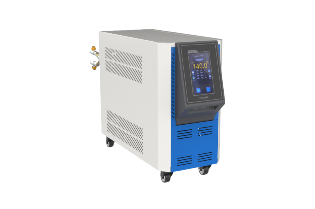
PID stands for Proportional, Integral, and Derivative—the controller uses these three mathematical “tools” to maintain a stable temperature. Unlike on/off controllers that operate in extreme conditions, PID-controlled mold temperature controllers progressively adjust heating output based on real-time data. This precision eliminates dead zones and reduces energy waste by 10%—here’s how each component works:
- Proportional (P): Corrects Current Temperature Error
The “P” component adjusts the heating output based on the difference between the actual and set temperatures. If the runner temperature is 5°F lower, the controller increases the heating power—but only enough to compensate for the temperature difference, not at full power. For example, if the set temperature is 350°F and the dead zone temperature drops to 340°F, the PID controller will increase the output by 10%, rather than jumping directly to 100% as an on/off controller would.
- Integral (I): Eliminates Persistent Cold Spots
Some dead zone temperatures are “stubborn,” remaining low even with minor heating adjustments. The “I” component tracks the duration of the error and slowly increases heating until the dead zone temperature rises. If the temperature at the runner bend remains below 2°F for 60 seconds, the PID controller will gradually increase heating until the temperature stabilizes.
- Derivative (D): Preventing Overheating
The “D” component predicts future temperature changes by observing the rate of temperature change. If the dead zone temperature rises from 340°F to 348°F within 5 seconds, the controller will reduce heating power prematurely, thus avoiding temperature overshoot problems common in switching systems. This not only maintains temperature stability but also reduces energy consumption.
Step-by-Step Setup to Address Cold Runner Dead Zone Issues
First, determine the location of the dead zone by scanning the runner during mold operation, looking for areas where the temperature is more than 5°F below the set value—these are the target temperatures. Mount one RTD sensor on the mold’s heating element and a second sensor directly on the dead zone. For hard-to-reach locations, use a flexible sensor probe. Avoid placing sensors near cooling pipes, as this can lead to inaccurate readings.
Then turn on the PID control mold temperature controller and enter your set value (e.g., 350°F). Press the “Auto-Tune” button—the controller will run a 5-10 minute test, gradually heating and cooling to learn the mold’s characteristics. Once complete, it will display the optimal P, I, and D values. For cold runners, the P value is expected to be between 5 and 10, the I value between 60 and 120 seconds, and the D value between 5 and 15 seconds. Then run the mold for 30 minutes using the new settings. Recheck the thermal imager; the dead zone temperature should be within ±1°F of the set temperature. If a region is still too cold, adjust the I value (increase it by 20 seconds) so the controller continues heating for a longer period. If overheating occurs, increase the D value (increase by 5 seconds) to predict temperature peaks earlier.
Real-world Application Cases of Cold Runner Molding Processes
While data is essential, real-world case studies from manufacturers better demonstrate how PID control mold temperature controllers are revolutionizing cold runner molding processes. Below are three case studies from Topstar customers, covering the automotive, medical, and consumer goods industries:
Case 1: Automotive Components
Problem: Cold-runner dead zones resulted in 15% scrap; to compensate, production cycles increased by 8%. Solution: Topstar PID-controlled mold temperature controller. Results: Scrap rate reduced to 3%; production cycles returned to normal; energy savings of 10%. Case 2: Syringe Housing
Challenge: FDA rejection due to inconsistent wall thickness (caused by ±2°F temperature fluctuations); traditional controllers could not maintain uniformity. Solution: Use a mold temperature controller with data logging capabilities. Result: Temperature uniformity improved to ±0.5°F; FDA rejection rate decreased from 7% to 0.3%.
Case 3: Toy Components
Challenge: Seasonal production stoppages; scrap rate as high as 12% in the fourth quarter. Solution: Use a mold temperature controller with adaptive tuning and ambient temperature compensation. Result: Annual scrap rate remained below 2%; no need to adjust setpoints between seasons.
PID Control Mold Temperature Controller Better Solve Cold Runner Dead Zones
Low-temperature dead zones in cold-runner injection molding not only affect product quality but also cause financial losses. Traditional on/off mold temperature controllers cannot meet the complex temperature requirements of cold runners, leading to increased scrap rates, longer production cycles, and energy waste. PID control mold temperature controllers use precise predictive technology to eliminate dead zones, improving efficiency by 10% and completely solving this problem.
TRENDING POSTS
- TOPSTAR Global Open Day 2025: Humanoid Robot Debuts, Pioneering a New Decade of Intelligent Manufacturing 2025/12/10
- Topstar Showcases TE II Electric Injection Molding Machines at InterPlas Thailand 2025 2025/12/10
- Topstar Expands Its Ecosystem Partnerships to Drive Smart Manufacturing Innovation 2025/12/10
- What factors can cause delays in the injection molding process of plastic molding machine? 2025/12/10
HOT TOPIC
- .ervo motor-driven linear robots
- •
- 1.0 guangdong topstar technology co. ltd
- 1.0 topstar china
- 1.0 topstar robot
- 11
- 160℃ mold temperature controller
- 170 ton injection molding machine
- 2
- 21
- 220-ton injection molding machine
- 23
- 260 ton injection molding machine
- 3 axis robot
- 3 axis robots
- 3 in 1 Compact Dehumidifying Dryer
- 3-axis robot
- 3-axis robots
- 39
- 41
- 460T injection molding machine
- 5-axis CNC machine
- 62
- 90 ton injection molding machine
- accuracy
- Air Chillers
- all electric injection molding machine
- all electric injection molding machines
- all-electric injection molding machine
- All-electric injection molding machines
- and overall production quality. Therefore
- AP-RubberPlas
- auto loader
- automated injection molding machine
- Automation changed engineering
- automation of injection molding robots
- automotive parts injection molding
- Auxiliary Equipment
- auxiliary machine
- Bench Injection Molding Machine
- cabinet dryer
- Cabinet dryer manufacturers
- Cabinet dryers
- chiller
- CNC Drilling Machine
- CNC Drilling Machines
- cnc engraving machine manufacturer
- cnc laser cutting machine manufacturer
- CNC machine
- CNC Machine Center
- CNC Machine for Sale
- CNC Machine Manufacturing
- CNC Machine Tool
- CNC machine tool product
- CNC Machining Center
- CNC wood carving machine
- Cooling system
- Cross-Walking Single Axis Servo Cylinder Robot
- Cross-Walking Single-Axis Servo Cylinder Robot
- Cross-Walking Three-Axis/Five-Axis Servo Driven Robot
- cross-walking three-axis/five-axis servo-driven robot
- Dehumidifier Dryer
- Dehumidifying Dryer
- delta parallel robot
- Desktop Injection Molding Machine
- Desktop injection molding machines
- Desktop Molding Machine
- desktop plastic injection machine
- Desktop Plastic Injection Molding Machine
- Digital Transformation
- direct clamp injection molding machine
- Direct clamp injection molding machines
- Dosing & mixing system
- Drilling Centers
- Drying and dehumidification system
- drying and dehumidifying equipment
- Drying and Dehumidifying System
- drying system
- effective and efficient. Cabinet dryers are also used in other industries where large quantities of material need to be dried
- efficient injection molding machine
- elbow hydraulic injection molding machines
- electric injection molding machine
- electric injection molding machines
- energy-efficient injection molding robot
- energy-efficient water chiller
- energy-efficient water chillers
- energy-saving injection molding machine
- etc. Among injection molding robots
- exhibition
- features of CNC machine
- Feeding And Conveying System
- Five Axis Machine Center
- Flexible Production Line
- Fully automatic injection molding machine
- Gathering Topstar
- giant injection molding machine
- GMU-600 5-Axis Machining Center
- Granulating & Recycling System
- granulator machine
- gravimetric blender
- Heavy duty injection molding machine
- High-precision electric molding machines
- high-precision plastic molding machines
- high-speed all electric injection molding machine
- high-speed electric injection molding machine
- High-Speed Packaging Injection Molding
- Honeycomb rotor dehumidifier
- Hopper Dryers
- horizontal injection molding machine
- Horizontal Injection Molding Machines
- Horizontal Injection Moulding Machine
- Horizontal Mixer manufacturer
- How The CNC Machine Works
- hybrid injection molding machine
- hydraulic injection molding machine
- Hydraulic Injection Molding Machines
- in this article
- Industrial AI
- Industrial Automation
- Industrial robot
- Industrial Robot Chinese brand
- industrial robot parts
- industrial robot supplier
- Industrial robots
- Industry Chain
- Injection Manipulator
- injection manipulator robot
- injection mold machines
- Injection molding
- Injection molding automation
- Injection Molding Automation Solution
- injection molding dryer
- Injection molding equipment
- injection molding hopper dryer
- Injection molding machine
- injection molding machine brand
- Injection Molding Machine Factory
- Injection Molding Machine Manufacture
- Injection molding machine manufacturer
- injection molding machine manufacturers
- Injection molding machine procurement
- injection molding machine robotic arm
- injection molding machine with a robot
- Injection molding machines
- injection molding material dehumidifying
- injection molding plant
- injection molding process
- Injection Molding Robot
- injection molding robot arm
- Injection molding robot automation
- Injection molding robotic arm
- injection molding robots
- injection moulding dryer
- Injection moulding machine
- injection moulding machines
- Injection Moulding Robots
- Injection Robot
- Injection robot arm
- Injection robot manufacturer
- Injection robot wholesale
- injection robots
- Intelligent Factory
- intelligent injection molding machines
- Intelligent Manufacturing
- intelligent mold temperature
- intelligent mold temperature controller
- Intelligent mould temperature controller
- InterPlas Thailand 2025
- Introducing Injection Robot
- It is the best choice for drying large quantities of material at once. Cabinetmakers use these machines because they are fast
- Large flow water type mold temperature controller
- large injection molding machine
- large injection molding machines
- Learn what industrial automation and robotics is
- linear robot
- linear robots
- low speed sound-proof granulator
- machine plastic molding
- make sure to add some! Improvements (2) Keyphrase in introduction: Your keyphrase or its synonyms appear in the first paragraph of the copy
- manipulator machine
- manufacturing
- Manufacturing Innovation
- medical grade injection molding machines
- Medical Injection Molding
- medical injection molding machine
- medical injection molding machines
- micro injection molding machine
- middle speed granulator
- Mini CNC machine manufacturers.
- mobile cover making machine
- Mold Temperature Control System
- mold temperature controller
- mold temperature controllers
- molding machine
- molding material Dehumidifying System
- mould temperature control system
- mould temperature controller
- mould temperature controllers
- New electric injection molding machine
- nitrogen dryer manufacturer
- nitrogen dryer system manufacturer
- Oil type mold temperature controller
- Oil type mold temperature controllers
- open day
- optical component injection molding
- Outbound links: No outbound links appear in this page. Add some! Images: No images appear on this page. Add some! Internal links: No internal links appear in this page
- packaging injection molding
- Packaging Solutions
- PET Preform injection molding
- phone case maker machine
- phone case making machine
- phone cover making machine
- PID Control Mold Temperature Controller
- plastic auto loader
- plastic bottle making machine
- plastic bottle manufacturing
- plastic bucket making machine
- plastic bucket manufacturing
- Plastic chair making machine
- plastic dryer for injection molding
- plastic forming equipment
- Plastic Granulators
- plastic hopper dryer
- plastic injection machine
- plastic injection machines
- plastic injection molding
- Plastic injection molding equipment
- Plastic injection molding machine
- Plastic Injection Molding Machines
- plastic injection moulding machine
- plastic injection moulding machines
- plastic injection robot
- plastic molding
- Plastic Molding Industry
- Plastic Molding machine
- plastic molding machine 1
- Plastic Molding Machines
- plastic molding press
- plastic moulding machine
- plastic phone case making machine
- plastic-molding machine
- powerful granulator
- Powerful Type Sound-Proof Granulator
- precision injection molding
- precision injection molding machines
- production of plastic seats
- pure water mould temperature controller
- Robot injection molding
- robot injection molding machine
- robot manufacturing companies
- Robotic arm for injection molding machine
- robotic injection molding machines
- robotics in injection molding
- SCARA robot
- SCARA robots
- Screw dosers
- Service-oriented manufacturing
- Servo Cylinder Robot
- servo driven robot
- Servo Driven Robots
- servo injection molding machine
- servo injection robots
- servo motor-driven linear robots
- servo-driven 3-axis robot
- Servo-driven injection molding machine
- Servo-Driven Robot
- Setup of injection machine
- Silicone Injection Molding Machine
- six-axis industrial robot
- Smart Manufacturing
- soundproof granulator
- Stainless Hopper Dryer
- Stainless Hopper Dryers
- star club
- swing arm robot
- take-out robot
- take-out robots
- Thailand 4.0
- the choice between servo-driven robots and hydraulic robots will have a certain impact on efficiency
- the most popular injection molding machine
- the type of injection molding robot
- TIC2000 Control System
- TMII injection molding machine
- toggle clamp injection molding machine
- Toggle Hydraulic Injection Molding Machines
- toggle injection molding machine
- Top 10 brands of injection robots
- Topstar
- Topstar Electric Injection Molding Machine InterPlas Thailand 2025 Smart Manufacturing Thailand 4.0
- Topstar Engineering
- Topstar Industrial Robots
- Topstar injection molding intelligent
- Topstar Scara Robots
- Useful Injection molding machine
- Vertical machining centers
- volumetric type blender
- water chiller
- water chillers
- water distributor
- water type mold temperature controller
- Water Type MoldTemperature Controller
- Water-Type Mould Temperature Controllers
- We often face choices when performing injection molding. We will choose the type of injection molding machine
- wholesale of injection molding machines
- x carve CNC
- 热门查询 点击次数 展示 排名 topstar