
TOPSTAR Cartesian Injection Robot Installation & Commissioning Guide
2026/10/14 By le zhan
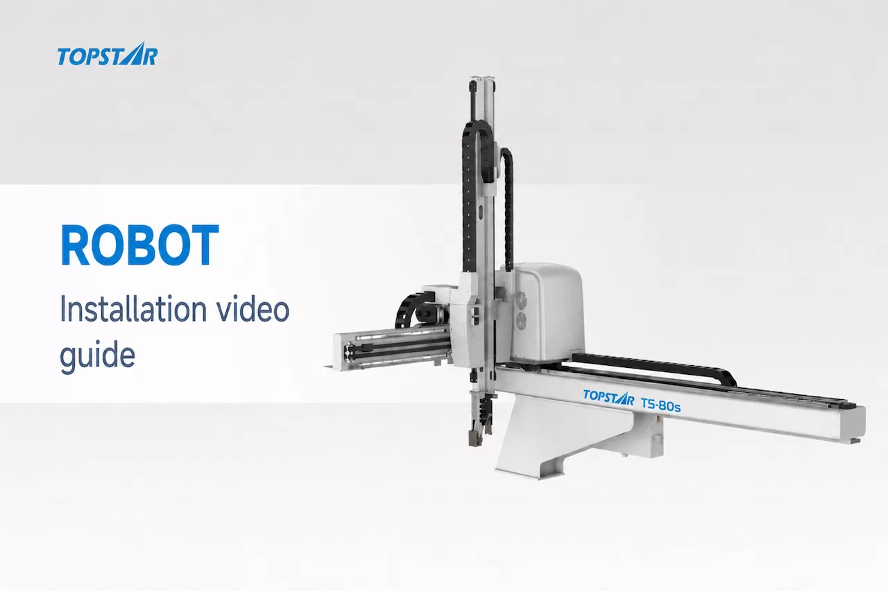
The installation Cartesian injection robot consists of four stages: equipment isolation and work area safety protection; preparation of the installation site; Cartesian injection robot installation and connection; and verification of synchronized operation with the injection molding machine. A correct and reliable installation requires ensuring that the mounting brackets are accurately positioned, that electrical and signal connections are properly matched, and that motion programs are verified before production begins.
In our installation video, we demonstrate the entire installation process using the T5-80s robot and the TS170 injection molding machine. This installation guide also provides detailed explanations of the installation steps and key inspection points for each stage. Be sure to refer to the installation drawings, wiring diagrams, and operating manual provided with the equipment to verify dimensions, connection details, and all configuration parameters.
What Should Be Checked Before Installing a Cartesian Injection Robot?
Pre-installation preparations begin with a thorough inspection and assessment of the entire production unit. The robot requires sufficient space for movement, an appropriate installation layout, and utilities (such as power and compressed air) that match its configuration. Before hoisting the robot into place, please complete the following two stages.
Ensure Safety in the Robot Installation Area
Before performing mechanical installation or wiring, the injection molding machine and robot must be isolated from hazardous energy sources. Follow the on-site “lockout” procedures to verify isolation and control stored energy that could cause unintended movement. (OSHA (Occupational Safety and Health Administration) guidelines on hazardous energy also list energy isolation and stored energy control as necessary precautions during relevant maintenance operations.)
Installation personnel must wear hard hats, safety shoes, and reflective vests. Personnel must remain clear of the robot’s path of movement, and a restricted installation area must be established. Before moving the robot, prepare for the lifting operation. Check the lifting equipment’s load capacity, inspect the lifting slings, and verify the lifting points specified in the equipment’s technical documentation. Ensure personnel stay clear of suspended equipment and prevent unauthorized activities from taking place within the lifting area.
Before proceeding, verify the following:
- The equipment’s isolation status has been verified.
- Restrictions have been implemented in the installation and lifting areas.
- The lifting equipment and lifting points meet requirements.
- The robot’s intended path of movement is unobstructed.
These precautions must be strictly observed throughout the entire installation and connection process. Controlled commissioning may only begin after the installation inspection has been completed.
(See video at approximately 0:36)
Prepare Tools and Check Clearance Around the Injection Molding Robot
The installation requires tools such as lifting slings, a multimeter, screwdrivers, wrenches, and sockets. In addition to these tools, you must also have the specified fasteners, installation components, connection fittings, and equipment drawings ready. Before installing the mounting bracket, check the clearance around the injection molding machine. Dry hoppers, overhead cranes, piping systems, and nearby equipment may interfere with the installation or the Cartesian injection robot’s subsequent movements.
Assess the robot’s expected working range (working envelope), including the paths to the mold area and the product placement area. (Note: A clear installation location does not necessarily guarantee sufficient operating clearance throughout the entire part-retrieval cycle!)
Next, check the on-site power supply against the robot’s nameplate and wiring diagrams. Any live-wire measurements must be performed by qualified personnel in accordance with standard procedures; be sure to disconnect the power supply before wiring.
Proceed with subsequent operations only after confirming that installation compatibility, motion clearance, tooling, and utility requirements are all met.
(See approximately 1:45 in the video for details.)
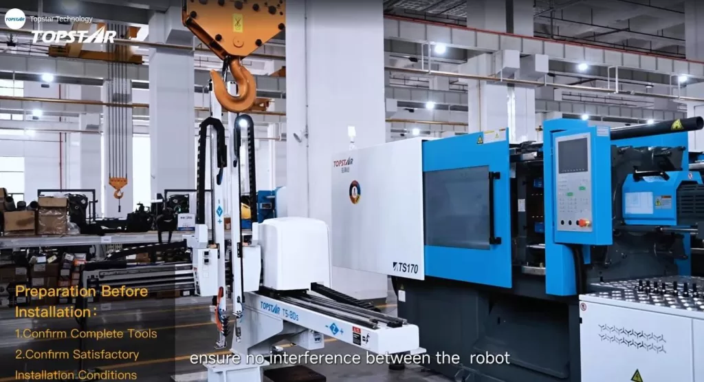
How to Connect, Commission, and Install a Cartesian Injection Robot?
Once the site is ready, complete the mechanical installation first, followed by connecting the power and control lines (utility connections). Next, verify each individual function before testing the coordinated motion sequences. The following two stages cover the installation, connection, and commissioning processes.
Installing the Injection Molding Robot and Connecting Various Lines
First, complete the mechanical installation and alignment, then connect the power supply, machine tool signal cables, compressed air lines, and the teach pendant.
Installation and Alignment of the Injection Molding Robot
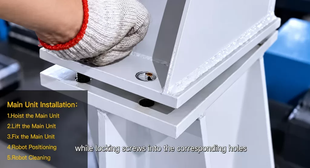
Verify the hole layout of the mounting bracket against the approved installation drawings for the injection molding machine to confirm the installation position, fastener specifications, and thread requirements. Note: If any missing or mismatched mounting holes are found, be sure to consult the equipment supplier or the responsible engineer before drilling holes or replacing the mounting bracket!
Use the approved lifting plan to hoist the robot above the mounting bracket. Align the mounting holes, install the specified fasteners, and ensure stable support during positioning. Check the robot’s position and parallelism against the manufacturer’s specified reference points, then tighten the fasteners to the specified torque. Clear away any debris generated during installation and ensure that no tools or loose parts are left around moving components.
(See approximately 3:27 in the video)
Electrical, Signal, and Pneumatic Connections
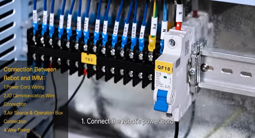
Before commissioning, verify all connections by referring to the equipment wiring diagram:
| Connection | Installation check |
|---|---|
| Electrical supply | Confirm the specified voltage, wiring arrangement, and protective grounding |
| Machine I/O | Match connections to the approved signal list and interface diagram |
| Compressed air | Connect to the designated inlet and set the specified pressure |
| Operation pendant | Connect securely and keep its cable clear of moving components |
Our video demonstrates the “Molding Complete” signal labeled “#13.” This definition applies only to the configuration shown in the demonstration; be sure to consult the actual equipment’s documentation before connecting signal wires.
Finally, secure the cables and air hoses, ensuring sufficient slack is provided, and keep them away from pinch points, sharp edges, and high-temperature surfaces.
(See approximately 4:46 in the video)
Pre-Production Robot Commissioning
We have listed five commissioning check items: Power-On, Manual Operation, Home Positioning, Signal Testing, and Simulated Operation. Please follow the specified commissioning procedure and perform these steps in sequence.
- Power-On and Air Supply Check:
Confirm that the controller starts up normally and check for any alarm indications. Inspect the pneumatic connections for leaks and verify that the operating pressure meets specifications. - Manual Movement Check:
With the motion area clear of obstacles, test each axis using the specified commissioning settings. Confirm that the movement directions are correct and ensure sufficient safety clearance between the robot and the injection molding machine, mold, hopper, and surrounding equipment. - Home Position Check:
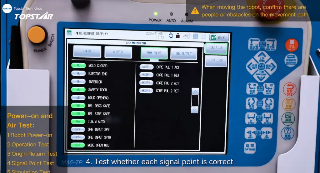
Execute the approved home position procedure. Confirm that all axes can establish their reference positions and that no collisions or abnormal movements occur during the process. - I/O (Input/Output) Check:
Use the monitoring screen on the teach pendant (handheld operator unit) to compare signal statuses with the machine’s actual operating conditions. Before proceeding to the next steps, identify and resolve any issues involving missing, reversed, or inconsistent signals. Complete the necessary emergency stop and safety interlock function verifications in accordance with the equipment’s technical documentation. - Simulation Run:
Test the coordinated motion sequence under controlled conditions. Verify that the robot enters the mold area only when permitted, completes the part retrieval operation, and returns to a safe position before the injection molding machine performs its next action.
Installation is considered complete when the robot is securely mounted, utilities meet specification requirements, reference positions are set, and the coordinated motion sequence between the injection molding machine and the robot has passed all necessary checks. The successful installation of a Cartesian injection molding robot signifies that all verification tasks for installation, connection, and coordinated operation have been completed prior to formal production.
(See the video at approximately 6:25–6:40)
This concludes the overview of the Cartesian injection molding robot installation; for further details, please watch the full video.(https://www.facebook.com/reel/1381934390245536)
TRENDING POSTS
- TOPS DAY 2026: Turning Industrial AI into Real-World Impact 2026/10/14
- Breaking Through the Full Scene-to-AI Link! Topstar Industrial Data Collection Matrix Achieves Major Technical Breakthro 2026/10/14
- TOPSTAR Selected in “Forbes China AI Top 50” and Wins “2026 Embodied AI Industry Benchmark Award” 2026/10/14
- Topstar Achieves ISO 13849 Functional Safety Certification for Robotics 2026/10/14
HOT TOPIC
- .ervo motor-driven linear robots
- •
- 1.0 guangdong topstar technology co. ltd
- 1.0 topstar china
- 1.0 topstar robot
- 11
- 160℃ mold temperature controller
- 170 ton injection molding machine
- 2
- 21
- 220-ton injection molding machine
- 23
- 260 ton injection molding machine
- 3 axis robot
- 3 axis robots
- 3 in 1 Compact Dehumidifying Dryer
- 3-axis robot
- 3-axis robots
- 39
- 4 axis robot
- 4-axis SCARA robot
- 41
- 460T injection molding machine
- 5-axis CNC machine
- 62
- 90 ton injection molding machine
- accuracy
- Air Chillers
- air-cooled chillers
- all electric injection molding machine
- all electric injection molding machines
- all-electric injection molding machine
- All-electric injection molding machines
- and overall production quality. Therefore
- AP-RubberPlas
- auto cooling system
- auto loader
- Auto Loaders
- automated injection molding machine
- Automation changed engineering
- automation of injection molding robots
- automotive parts injection molding
- Auxiliary Equipment
- auxiliary machine
- Bench Injection Molding Machine
- cabinet dryer
- Cabinet dryer manufacturers
- Cabinet dryers
- cartesian coordinate robot
- Cartesian Coordinate Robots
- Cartesian injection robot
- Cartesian robot
- Central Feeding System
- Central Feeding Systems
- chiller
- CNC Drilling Machine
- CNC Drilling Machines
- cnc engraving machine manufacturer
- cnc laser cutting machine manufacturer
- CNC machine
- CNC Machine Center
- CNC Machine for Sale
- CNC Machine Manufacturing
- CNC Machine Tool
- CNC machine tool product
- CNC Machining Center
- CNC wood carving machine
- Compact Dehumidifying Dryer
- Cooling system
- Cross-Walking Single Axis Servo Cylinder Robot
- Cross-Walking Single-Axis Servo Cylinder Robot
- Cross-Walking Three-Axis/Five-Axis Servo Driven Robot
- cross-walking three-axis/five-axis servo-driven robot
- Dehumidifier Dryer
- Dehumidifying Dryer
- dehumidifying dryers
- delta parallel robot
- Desktop Injection Molding Machine
- Desktop injection molding machines
- Desktop Molding Machine
- desktop plastic injection machine
- Desktop Plastic Injection Molding Machine
- detachable autoloader
- Digital Transformation
- direct clamp injection molding machine
- Direct clamp injection molding machines
- Dosing & mixing system
- Drilling Centers
- Drying and dehumidification system
- drying and dehumidifying equipment
- Drying and Dehumidifying System
- drying system
- effective and efficient. Cabinet dryers are also used in other industries where large quantities of material need to be dried
- efficient injection molding machine
- elbow hydraulic injection molding machines
- electric injection molding machine
- electric injection molding machines
- energy-efficient injection molding robot
- energy-efficient water chiller
- energy-efficient water chillers
- energy-saving injection molding machine
- etc. Among injection molding robots
- exhibition
- features of CNC machine
- Feeding And Conveying System
- Five Axis Machine Center
- Flexible Production Line
- Fully automatic injection molding machine
- Gathering Topstar
- giant injection molding machine
- GMU-600 5-Axis Machining Center
- Granulating & Recycling System
- granulator machine
- gravimetric blender
- Heavy duty injection molding machine
- Heavy-Duty Take-Out Robot
- High-precision electric molding machines
- high-precision plastic molding machines
- high-speed all electric injection molding machine
- high-speed electric injection molding machine
- High-Speed Packaging Injection Molding
- Honeycomb rotor dehumidifier
- hopper dryer
- Hopper Dryers
- horizontal injection molding machine
- Horizontal Injection Molding Machines
- Horizontal Injection Moulding Machine
- Horizontal Mixer manufacturer
- How The CNC Machine Works
- hybrid injection molding machine
- hydraulic injection molding machine
- Hydraulic Injection Molding Machines
- in this article
- Industrial AI
- Industrial Automation
- Industrial robot
- Industrial Robot Chinese brand
- industrial robot parts
- industrial robot supplier
- Industrial robots
- Industry Chain
- Injection Manipulator
- injection manipulator robot
- injection mold machines
- Injection molding
- Injection molding automation
- Injection Molding Automation Solution
- injection molding dryer
- Injection molding equipment
- injection molding hopper dryer
- Injection molding machine
- injection molding machine brand
- Injection Molding Machine Factory
- Injection Molding Machine Manufacture
- Injection molding machine manufacturer
- injection molding machine manufacturers
- Injection molding machine procurement
- injection molding machine robotic arm
- injection molding machine with a robot
- Injection molding machines
- injection molding material dehumidifying
- injection molding plant
- injection molding process
- Injection Molding Robot
- injection molding robot arm
- Injection molding robot automation
- Injection molding robotic arm
- injection molding robots
- injection molding whole plant
- injection moulding dryer
- Injection moulding machine
- injection moulding machines
- Injection Moulding Robots
- Injection Robot
- Injection robot arm
- Injection robot manufacturer
- Injection robot wholesale
- injection robots
- Intelligent Factory
- intelligent injection molding machines
- Intelligent Manufacturing
- intelligent mold temperature
- intelligent mold temperature controller
- Intelligent mould temperature controller
- intelligent whole plant solution
- InterPlas Thailand 2025
- Introducing Injection Robot
- It is the best choice for drying large quantities of material at once. Cabinetmakers use these machines because they are fast
- Large flow water type mold temperature controller
- large injection molding machine
- large injection molding machines
- Learn what industrial automation and robotics is
- linear robot
- linear robots
- low speed sound-proof granulator
- machine plastic molding
- make sure to add some! Improvements (2) Keyphrase in introduction: Your keyphrase or its synonyms appear in the first paragraph of the copy
- manipulator machine
- manufacturing
- Manufacturing Innovation
- medical grade injection molding machines
- Medical Injection Molding
- medical injection molding machine
- medical injection molding machines
- micro injection molding machine
- middle speed granulator
- Mini CNC machine manufacturers.
- mobile cover making machine
- Mold Temperature Control System
- mold temperature controller
- mold temperature controllers
- molding machine
- molding material Dehumidifying System
- mould temperature control system
- mould temperature controller
- mould temperature controller
- mould temperature controllers
- New electric injection molding machine
- Nitrogen Dryer
- nitrogen dryer manufacturer
- nitrogen dryer system manufacturer
- Oil type mold temperature controller
- Oil type mold temperature controllers
- open day
- optical component injection molding
- Optical-grade dehumidifying dryer
- Outbound links: No outbound links appear in this page. Add some! Images: No images appear on this page. Add some! Internal links: No internal links appear in this page
- packaging injection molding
- Packaging Solutions
- PET Preform injection molding
- phone case maker machine
- phone case making machine
- phone cover making machine
- PID Control Mold Temperature Controller
- plastic auto loader
- plastic bottle making machine
- plastic bottle manufacturing
- plastic bucket making machine
- plastic bucket manufacturing
- Plastic chair making machine
- plastic dryer for injection molding
- plastic forming equipment
- Plastic Granulator
- Plastic Granulators
- plastic hopper dryer
- plastic injection machine
- plastic injection machines
- plastic injection molding
- Plastic injection molding equipment
- Plastic injection molding machine
- Plastic Injection Molding Machines
- plastic injection moulding machine
- plastic injection moulding machines
- plastic injection robot
- plastic molding
- Plastic Molding Industry
- Plastic Molding machine
- plastic molding machine 1
- Plastic Molding Machines
- plastic molding press
- plastic moulding machine
- plastic phone case making machine
- plastic-molding machine
- powerful granulator
- Powerful Type Sound-Proof Granulator
- precision injection molding
- precision injection molding machines
- production of plastic seats
- pure water mould temperature controller
- Robot injection molding
- robot injection molding machine
- robot manufacturing companies
- Robotic arm for injection molding machine
- robotic injection molding machines
- robotics in injection molding
- SCARA robot
- SCARA robots
- Screw dosers
- Service-oriented manufacturing
- Servo Cylinder Robot
- servo driven robot
- Servo Driven Robots
- servo injection molding machine
- servo injection robots
- servo motor-driven linear robots
- servo-driven 3-axis robot
- Servo-driven injection molding machine
- Servo-Driven Robot
- Setup of injection machine
- Silicone Injection Molding Machine
- six-axis industrial robot
- Smart Manufacturing
- soundproof granulator
- Sprue Picker
- Stainless Hopper Dryer
- Stainless Hopper Dryers
- star club
- swing arm robot
- T1 Cartesian injection robot
- take-out robot
- take-out robots
- Thailand 4.0
- the choice between servo-driven robots and hydraulic robots will have a certain impact on efficiency
- the most popular injection molding machine
- the type of injection molding robot
- TIC2000 Control System
- TMII injection molding machine
- toggle clamp injection molding machine
- Toggle Hydraulic Injection Molding Machines
- toggle injection molding machine
- Top 10 brands of injection robots
- Topstar
- Topstar Electric Injection Molding Machine InterPlas Thailand 2025 Smart Manufacturing Thailand 4.0
- Topstar Engineering
- Topstar Industrial Robots
- Topstar injection molding intelligent
- Topstar Scara Robots
- Useful Injection molding machine
- Vertical machining centers
- volumetric type blender
- Washing Machine Case Molding Solution
- water chiller
- water chillers
- water distributor
- water type mold temperature controller
- Water Type MoldTemperature Controller
- Water-Cooled Chillers
- Water-cooled Mold Temperature Controller
- water-type mold temperature controller
- Water-Type Mould Temperature Controllers
- We often face choices when performing injection molding. We will choose the type of injection molding machine
- wholesale of injection molding machines
- x carve CNC
- 热门查询 点击次数 展示 排名 topstar